Chain connecting element with security connector piece

A technology of chain connection and components, applied in the direction of chain buckles, shackles, etc., can solve problems such as increased manufacturing costs

Inactive Publication Date: 2015-05-20
THIELE GMBH & CO KG
View PDF10 Cites 4 Cited by
  • Summary
  • Abstract
  • Description
  • Claims
  • Application Information

AI Technical Summary

Problems solved by technology

A disadvantage, however, is the increased manufacturing costs and the fact that a different component is required due to the locking ball, which increases the component variety

Method used


Image

  • Chain connecting element with security connector piece
  • Chain connecting element with security connector piece
  • Chain connecting element with security connector piece

Examples


Embodiment Construction

[0029] In the various figures, the same or similar components are provided with the same reference numerals, even if a repeated description is omitted for reasons of simplification.

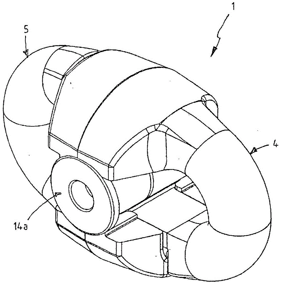
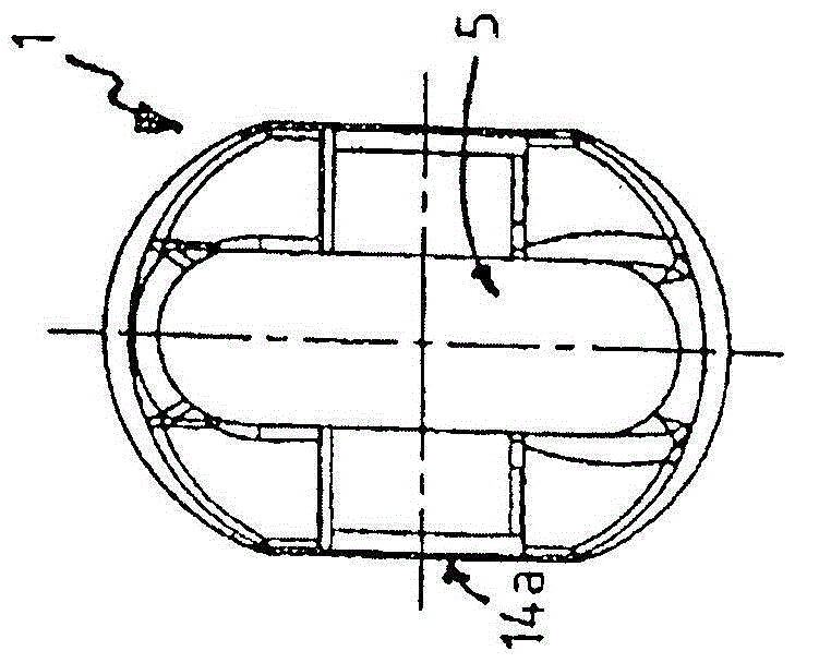
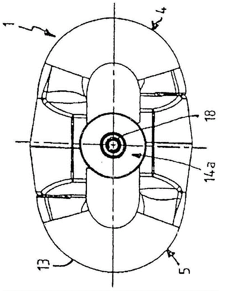
[0030] FIGS. 1 a to 3 f each chain link element 1 - 3 has two identical chain link brackets 4 , 5 coupled via their side legs, which are of identical design in all the figures. A side leg 6 of each chain link bracket 4 , 5 now has a neck section 7 and a tenon 8 thickened relative to the neck section. A neck recess 10 and a tenon recess 11 are correspondingly provided on the other side leg 9 of the link bow 4 , 5 . According to the invention, on each tenon 8 and on each tenon recess 11 there is provided a side surface 12 conically formed with respect to the longitudinal mid-plane MLD of the tenon 8 (see also Figure 4 and Figure 5). Furthermore, the length L of the leg 6 is dimensioned such that the transverse mid-plane MQE of the chain connection elements 1 - 3 intersects the tenon 8 .

[003...


PUM


Abstract

The invention relates to a chain connecting element (1) which has two link bow sections (4, 5), which can be coupled via their limbs (6), and a connector piece (50), which can be inserted transversally between the limbs (9), one limb (9) of each link bracket (4, 5) having a neck section (7) and a journal (8) that is thicker relative thereto, a neck recess (10) and a journal recess (11) being provided on the other, opposite lying limb (9) in a corresponding manner, wherein the two link bow sections (5), which are inserted into one another, can be locked by the connector piece (50) and the connector piece (50) is formed by a bolt, a sleeve and a spring journal. The connector piece (50) is of mirror-symmetrical design, an outer-lying bearing sleeve (51) being provided on each side of said piece for form-locked locking engagement in the link bow sections (4, 5) and an inner-lying locking bolt (53) has a spring journal (26) on each of its ends, wherein a clamping pin (63) can be inserted or retracted on both sides of the locking bolts (53) and secures each of the spring journals (26) in a respective bearing sleeve (51) in form-locked manner.

Description

technical field [0001] The invention relates to a chain connecting element according to the preamble of claim 1 . Background technique [0002] The chain connecting element can especially be used for high-power round steel chains, such as those used in underground mining. It is known that in the case of chain connection elements in the form of tipping construction, dismantling after use presents difficulties because the long tensioning pins pass through the opposite side legs and webs of the two element halves. rust in the holes extending obliquely in the plane of the link. Furthermore, the tensioning pin, like the web arranged between the element halves, is subjected to shear loads due to the load of the two element halves of the chain connecting element, which additionally makes it easier to withdraw the tensioning pin from the elongated hole. difficulty. In addition, long punches are required for retracting the tensioning pin, which are subjected to strong bending load...

Claims


Application Information

Patent Timeline
Patent Type & Authority Applications(China)
IPC IPC(8): F16G15/04
CPCF16G15/02F16G15/04
Inventor E·布罗齐亚克
Owner THIELE GMBH & CO KG
Why Eureka
Try Eureka