
Gearbox device, in particular for actuators in motor vehicles

A technology of transmission mechanism and adjustment device, which is applied in the direction of power control mechanism, wing control mechanism, hoisting device, etc., which can solve the problems of inability to suppress axial impact, and achieve the effect of simple connection and compact structure

Inactive Publication Date: 2006-12-20
ROBERT BOSCH GMBH
View PDF1 Cites 0 Cited by
  • Summary
  • Abstract
  • Description
  • Claims
  • Application Information

AI Technical Summary

Problems solved by technology

However, it still cannot suppress the axial shock

Method used


Image

  • Gearbox device, in particular for actuators in motor vehicles
  • Gearbox device, in particular for actuators in motor vehicles
  • Gearbox device, in particular for actuators in motor vehicles

Examples


Embodiment Construction

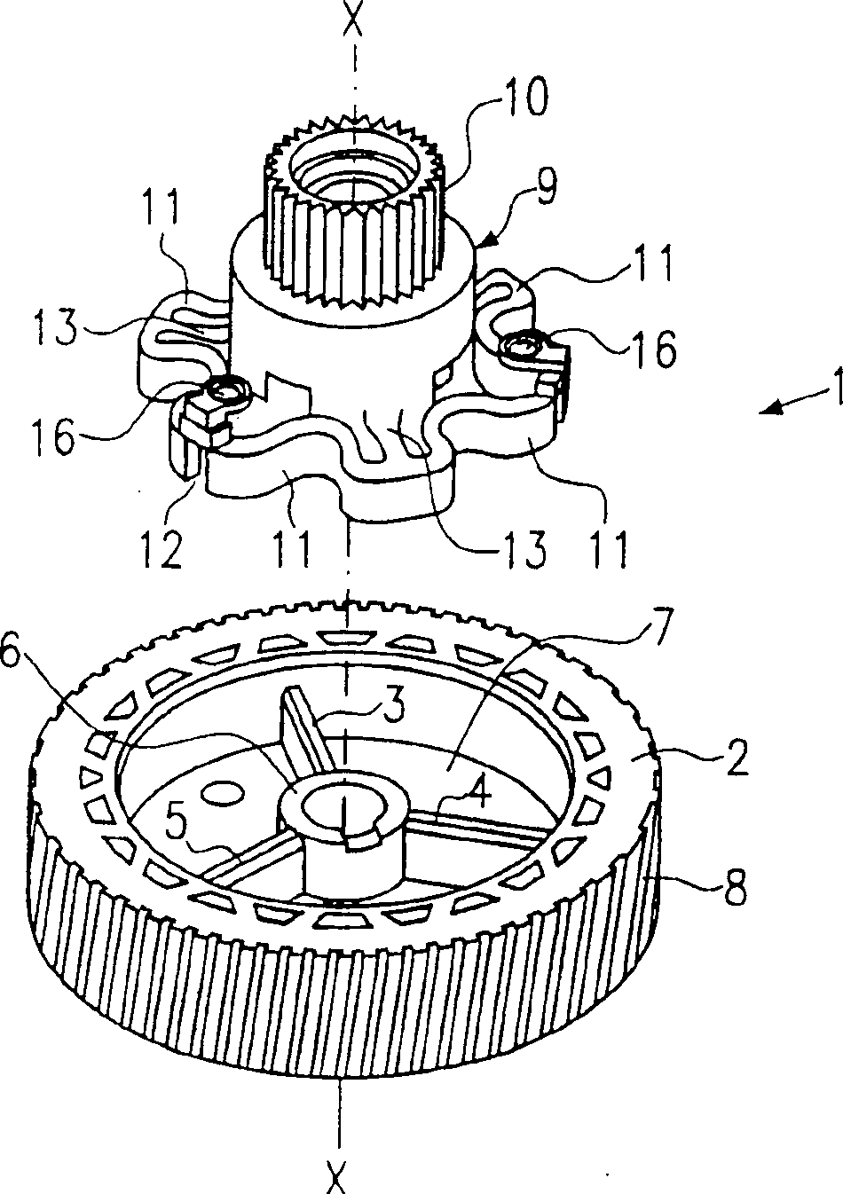
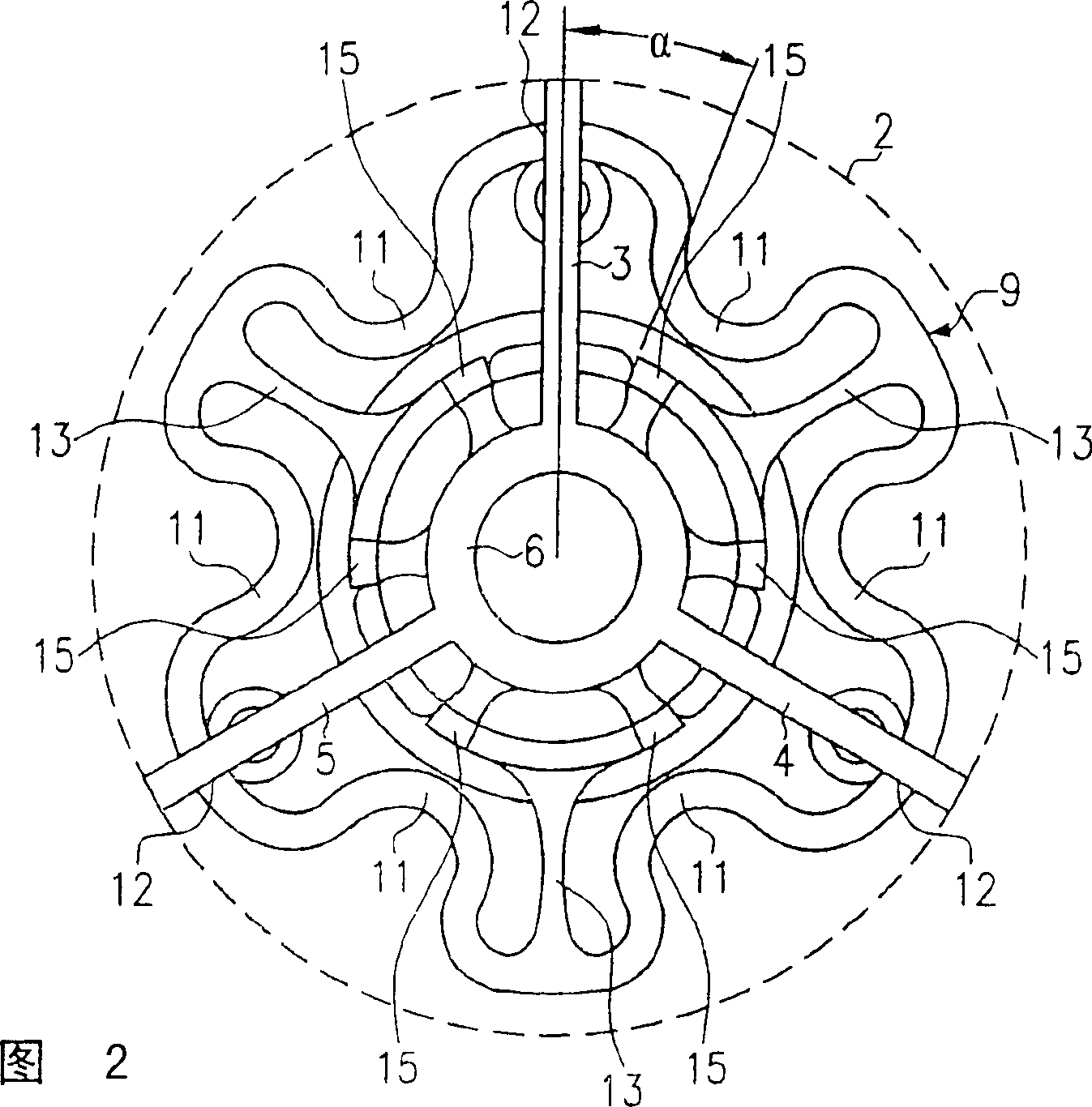
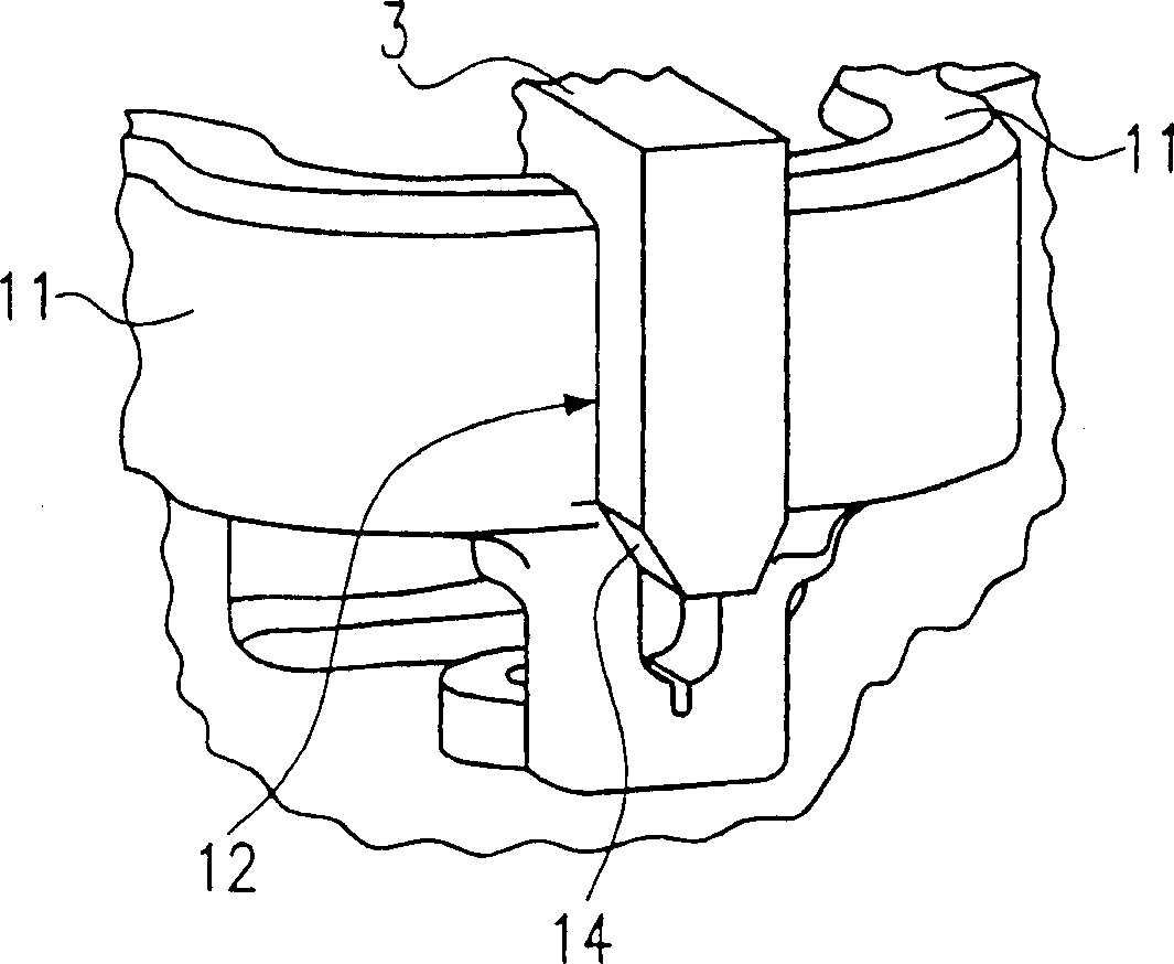
[0019] Below, refer to Figures 1 to 3 A transmission mechanism according to a first embodiment of the present invention will be described.

[0020] Such as figure 1 It is shown that the transmission mechanism 1 comprises a first transmission member in the form of a spur gear 2 and a second transmission member in the form of a synchronizer 9 . The spur gear 2 is designed essentially as a ring gear and has ribs 3 , 4 , 5 which are connected to a central bore 6 for supporting the spur gear 2 on a bearing pin not shown superior. On the outer circumference of the spur gear 2 is formed a gear tooth 8 in the shape of a helical tooth, which is driven by an electric motor via a worm. Furthermore, the spur gear 2 has a base 7 at its end in the axial direction.

[0021] Synchronizing element 9 includes a pinion 10 and is likewise supported on the bearing pin, not shown. Furthermore, an integral damping element is formed on the synchronization element 9 in the form of a plurality o...


PUM


Abstract

The invention relates to a gearbox device, comprising a first gearbox component (2) and a second gearbox component (9), which are connected to each other such as to be able to rotate, whereby a damping element (11) is arranged between the first and the second gearbox component (2, 9), characterised in that the damping element (11) is integrally embodied with the first and / or second gearbox element (2, 9) and the damping element (11) provides damping in the circumferential direction of the gearbox components and in the axial direction (X-X) of the gearbox components.

Description

technical field [0001] The invention relates to a transmission for an adjustment device in a motor vehicle. Background technique [0002] Transmissions are used, for example, in adjustment devices in motor vehicles, such as power windows or sliding sunroofs driven by means of electric motors. In particular, electric motors are used in this connection, which are adjusted between open-closed end positions, for example for vehicle windows, by means of a transmission. Since vibrations and undesired shock loads can occur when the starter motor is actuated or when the stop is reached in the end position, it is known to provide a damping element between two transmission components. Figure 6 is a well known structure of this type. In this case, three rubber-elastic damping elements 24 , 25 , 26 are arranged between an adjusting wheel 22 , which is driven by an electric motor via a worm, and a synchronization element 23 . Among them, the damping elements 24, 25, 26 can suppress vi...

Claims


Application Information

Patent Timeline
Patent Type & Authority Patents(China)
IPC IPC(8): E05F15/16F16D3/62F16F15/124F16H1/16F16H55/14F16F15/12
CPCE05F15/697E05F15/1692F16H55/14E05Y2900/55F16D3/62F16F15/124F16F15/1201B60K17/04
Inventor R·兰佩特F·塔施W·芬佩尔W·豪泽克尔M·格德克G·凯尔马特
Owner ROBERT BOSCH GMBH
Learn More