Guide and guard guide roller openness adjusting device

A technology for adjusting device and opening degree, which is applied in the field of steel rolling, can solve problems such as wear and tear at the end of the guide roller, and damage to the cooperation between the guide roller and the worm wheel, and achieve the goal of maintaining the opening degree of the guide roller, relieving stress concentration, and ensuring surface quality Effect

Inactive Publication Date: 2015-05-27
JIANGSU LIANFENG ENERGY EQUIP
View PDF5 Cites 1 Cited by
  • Summary
  • Abstract
  • Description
  • Claims
  • Application Information

AI Technical Summary

Problems solved by technology

[0004] At present, the depth of the groove on the general worm wheel is 5-10mm, the end of the guide roller shaft matched with the groove is 5-12mm, and the contact area between the two is generally 320mm 2 , and generally made into a circular cross-section, then, due to the small contact area, during the rolling process, due to the continuous impact of the guide roller by the rolled piece, the cooperation between the guide roller and the worm wheel will be quickly destroyed. For example, the assembly surface of the card slot is pitted or broken, and the end of the guide roller is severely worn, so that the opening of the guide roller cannot be maintained at the set value, resulting in a larger opening and folds on the surface of the product , ears and other defects seriously affect the surface quality of the product. In severe cases, the rolling process cannot be carried out smoothly, and a series of problems in the replacement of guides and guards will be derived, which will seriously affect the production efficiency.

Method used


Image

  • Guide and guard guide roller openness adjusting device

Examples


Embodiment Construction

[0022] The present invention will be described in detail below in conjunction with the accompanying drawings, so that those of ordinary skill in the art can implement it after referring to this specification.

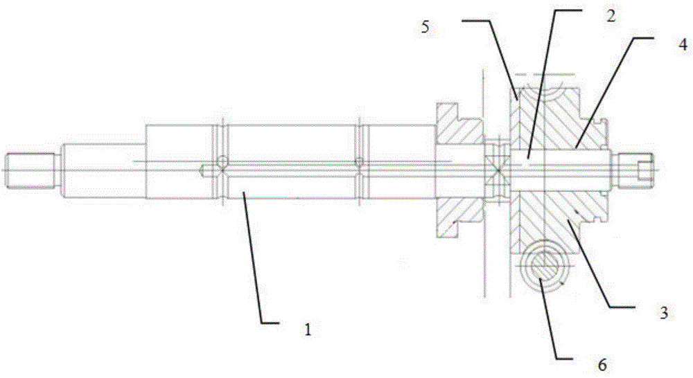
[0023] Such as figure 1 As shown, a device for adjusting the opening degree of guide rollers, including:

[0024] A guide roller, which includes a guide roller body and a guide roller shaft 1, the guide roller body is sleeved on the outside of the guide roller shaft 1 and is driven by the guide roller shaft 1 to move in a circumferential direction, wherein the guide roller shaft 1 It is an eccentric shaft, and the end of the guide roller shaft 1 is provided with a connecting shaft 2;

[0025] The worm wheel 3 is movably connected with the connecting shaft 2 at the end of the guide roller shaft 1, and the movably connecting mode is: the worm wheel 3 is provided with a groove 4 matching the connecting shaft 2, and the connecting The shaft 2 is embedded in the groove 4, ...


PUM

PropertyMeasurementUnit
thicknessaaaaaaaaaa
depthaaaaaaaaaa
lengthaaaaaaaaaa

Abstract

The invention discloses a guide and guard guide roller openness adjusting device which comprises a guide roller, a worm gear and a worm rod. The guide roller comprises a guide roller body and a guide roller shaft, wherein the guide roller body is arranged outside the guide roller shaft in a sleeving mode and is driven by the guide roller shaft to move peripherally, the guide roller shaft is an eccentric shaft, a connecting shaft is arranged at the end of the guide roller shaft, and the worm gear is movably connected with the connecting shaft arranged at the end of the guide roller shaft. A movable connection method is that a groove matched with the connecting shaft is formed in the worm gear, the connecting shaft is embedded into the groove to enable the guide roller shaft to move along with the worm gear, the worm rod is in pivot connection with the outer part of the worm gear, and the worm gear can move along with the worm rod. In addition, a gasket is further arranged on the worm gear, and an opening with the consistent shape and size as those of the groove is formed in the gasket; thus, the contact area between the connecting shaft at the end of the guide roller shaft and the worm gear is enlarged, the stress can be dispersed, impact force to a rolled piece is reduced, and the openness of the guide roller can keep unchanged.

Description

technical field [0001] The invention relates to the technical field of steel rolling, in particular to a device for adjusting the opening degree of guide rollers. Background technique [0002] The guide is a device installed before and after the roll pass to help the rolled piece enter and exit the roll pass accurately and stably according to the predetermined direction and state during the section steel rolling process. At present, the guide with the world's advanced level has SMS Guides, Morgan guides, Ashlow guides, Danieli guides and FRS guides, etc., all kinds of guides have their own characteristics, but the overall goal is to ensure the quality of wire products. [0003] Among them, the adjustment of the opening degree of the FRS type guide and guide roller is realized through the worm gear mechanism. Movement, so as to realize the adjustment of the opening degree of the guide roller. The torque transmission between the worm wheel and the guide roller shaft is reali...

Claims


Application Information

Patent Timeline
Patent Type & Authority Applications(China)
IPC IPC(8): B21B39/14
Inventor 李刚陈忠杜龑
Owner JIANGSU LIANFENG ENERGY EQUIP
Why Eureka
Try Eureka