Deep hole O-shaped sealing ring sleeving mounting machine

An O-ring and installation machine technology, which is applied in metal processing, metal processing equipment, manufacturing tools, etc., can solve problems such as the inability to directly support deep-hole sleeve O-rings, etc.

Active Publication Date: 2015-05-27
QUANSTAR PRECISION MACHINERY SHANGHAI
View PDF5 Cites 2 Cited by
  • Summary
  • Abstract
  • Description
  • Claims
  • Application Information

AI Technical Summary

Problems solved by technology

[0003] The purpose of the present invention is to solve the problem that the O-ring jaws in the prior art cannot directly support the deep-hole sleeve O-ring, but can only rely on manual direct casing or first put the O-ring on the transition sleeve and then manually The above-mentioned problems in casing one by one

Method used


Image

  • Deep hole O-shaped sealing ring sleeving mounting machine
  • Deep hole O-shaped sealing ring sleeving mounting machine
  • Deep hole O-shaped sealing ring sleeving mounting machine

Examples


Embodiment Construction

[0005] The present invention will be described in detail below in conjunction with the embodiments.

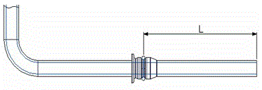
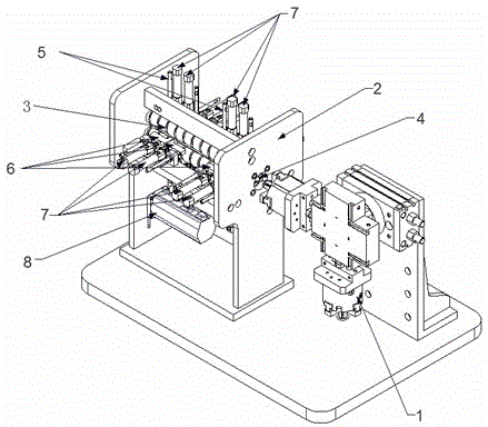
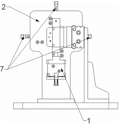
[0006] The figure includes a lifting and rotating four-claw support mechanism 1, which is characterized in that: a mounting machine frame 2 is arranged on one side of the lifting and rotating four-claw support mechanism, and four screw rods 3 are arranged in parallel on the frame. The rods are distributed in the four corners of a horizontal rectangle. There are casings 4 inside the four screw rods. The sleeves are tangent to the four screw rods. Two groups of support mechanisms 5 are arranged on the front and back of the frame, and the support mechanisms are opposite to the sleeve pipes. One end of the sleeve pipe on the frame is opposite to the lifting and rotating four-claw supporting mechanism station. Each set of support mechanism has four pairs of support feet, four pairs of support feet are divided into two pairs and arranged parallel to the left and right. The two pairs...


PUM


Abstract

The invention relates to a deep hole O-shaped sealing ring sleeving mounting machine. The machine comprises a lifting rotating four-claw supporting and picking mechanism. The machine is characterized in that a mounting device rack is arranged at one side of the lifting rotating four-claw supporting and picking mechanism; four lead screws are arranged in parallel to the rack and are distributed in four corners of a horizontal rectangle; a sleeve is arranged at the inner side of each four lead screw and is tangent to each of the four lead screws; two groups of supporting mechanisms opposite to the sleeves are arranged at the front and back of the rack; the sleeves can be alternatively clamped and positioned through the supporting mechanisms. The machine has the advantages that original operation of manually sleeving an O-shaped ring is replaced, and thus the working efficiency and accuracy are qualitatively increased; in addition, the automation is achieved, so that the labor intensity of workers is reduced; the machine has a good market prospect under the large automatic production background in the current product; the machine is free of a complex structure, and the function can be performed only after the processing precision and the corresponding strength are ensured.

Description

technical field [0001] The invention relates to a deep hole sleeve O-ring installation machine. Background technique [0002] In industrial production, there will be many structures where O-rings need to be installed. On the assembly line, the O-ring jaws are generally used to directly support the O-rings, and then the O-rings are directly placed in the sealing grooves that need to be installed. However, if the position where the O-ring needs to be installed is relatively deep (see figure 1 ), figure 1 As shown in the figure, because L is relatively long, it is a deep-hole sleeve O-ring, so it is no longer possible to use the traditional O-ring jaws to directly support and install the sleeve. At present, most of the O-rings are manually clamped on both sides and then directly placed on the product. It is time-consuming and the accuracy cannot be guaranteed, and automatic production cannot be realized. Therefore, it is urgent to design a device that can complete the install...

Claims


Application Information

Patent Timeline
Patent Type & Authority Applications(China)
IPC IPC(8): B23P19/08
CPCB23P19/001B23P19/084
Inventor 梁世春顾春亮王国成
Owner QUANSTAR PRECISION MACHINERY SHANGHAI
Why Eureka
Try Eureka