Arrangement structure of underwater robot propelling device

An underwater robot and propulsion device technology, which is applied in the direction of propulsion components, ship propulsion, underwater ships, etc., can solve the problems of difficult to meet the requirements of the detection and use environment of detection equipment, large turning radius, and long turning distance.

Inactive Publication Date: 2015-05-27
SHENYANG INST OF AUTOMATION - CHINESE ACAD OF SCI
View PDF6 Cites 24 Cited by
  • Summary
  • Abstract
  • Description
  • Claims
  • Application Information

AI Technical Summary

Problems solved by technology

[0002] Traditional underwater robots are all in the shape of a slender cylinder. Usually, the propeller is arranged at the stern of the underwater robot, and there is also a propulsion control rudder system at the stern of the underwater robot. Although this arrangement has high propulsion efficiency , but this arrangement must be able to control the heading and navigation attitude when the underwater robot has a certain forward speed, and the underwater robot often has the disadvantages of large turning radius and long turning distance when turning
In this case, it will take a lot of time, manpower and material resources to complete the search and positioning of the specific target area.
In addition, when the underwater robot is sailing at a low speed (the speed is lower than 2 knots), it is often difficult to play the role of the propulsion control rudder system at the stern of the underwater robot, and it cannot effectively control the navigation attitude ability, and it is difficult to meet the detection and use environment of the detection equipment. Require

Method used


Image

  • Arrangement structure of underwater robot propelling device
  • Arrangement structure of underwater robot propelling device
  • Arrangement structure of underwater robot propelling device

Examples


Embodiment Construction

[0017] The present invention will be described in further detail below in conjunction with the accompanying drawings.

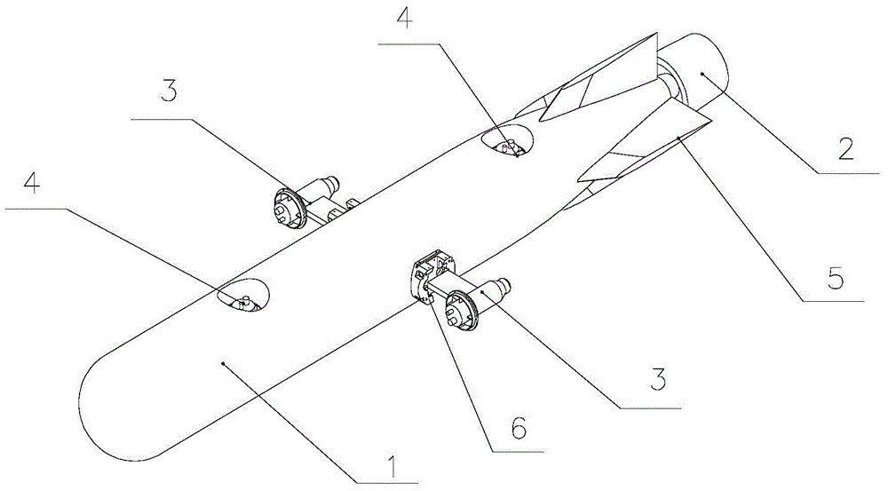
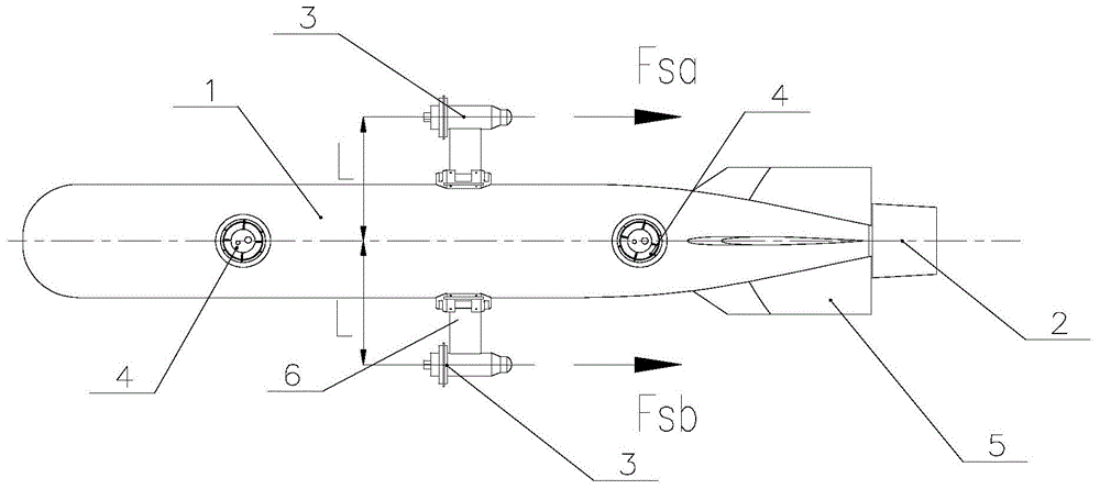
[0018] like figure 1 As shown, the layout structure of the underwater robot propulsion device described in the present invention includes: the stern of the underwater robot vehicle 1 is provided with a stern thruster 2 and a stern navigation control rudder system 5 for navigation control, and the underwater robot Two horizontal propellers 3 are symmetrically arranged on both sides of the vehicle 1 along the axial direction, and the horizontal propellers 3 are fixed on the vehicle 1 of the underwater robot through a fixing seat 6 . The horizontal propeller 3 has the equivalent forward and reverse propulsion force, which can make the underwater robot vehicle 1 have a smaller turning radius, and can also realize turning in situ.

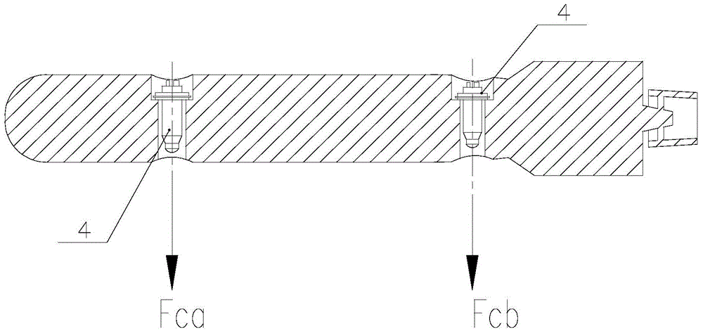
[0019] The bow and stern of the underwater robot vehicle 1 are respectively provided with through holes, and two vertical propellers...


PUM


Abstract

The invention relates to an arrangement structure of an underwater robot propelling device for controlling navigation posture of an underwater robot. The arrangement structure comprises a stern propeller and a stern navigation control rudder system arranged at the stern part of a navigation body of the underwater robot, and further comprises horizontal propellers symmetrically arranged at the two sides of the navigation body of the underwater robot in the axial direction, and vertical propellers respectively arranged at the fore part and the stern part of the navigation body of the underwater robot. The horizontal propellers are fixed at the two sides of the navigation body of the underwater robot along the axial direction through fixing bases. Through holes are respectively formed in the bow part and the stern part of the navigation body of the underwater robot; and the vertical propellers are respectively fixed in the through holes, and are symmetrically arranged around the geometric center line of the navigation body of the underwater robot. The navigation posture of the navigation body of the underwater robot can be effectively controlled in steering and low-speed navigation of the underwater robot.

Description

technical field [0001] The invention relates to an arrangement structure of an underwater robot propulsion device for controlling the navigation attitude of the underwater robot. Background technique [0002] Traditional underwater robots are in the shape of a slender cylinder, usually the propeller is arranged at the stern of the underwater robot, and there is also a propulsion control rudder system at the stern of the underwater robot, although this arrangement has high propulsion efficiency , but this arrangement must be able to control the heading and navigation attitude when the underwater robot has a certain forward speed, and the underwater robot often has the disadvantages of large turning radius and long turning distance when turning. In this case, it will cost a lot of time, manpower and material resources to complete the search and positioning of the specific target area. In addition, when the underwater robot is sailing at a low speed (the speed is lower than 2 ...

Claims


Application Information

Patent Timeline
IPC IPC(8): B63H5/00B63C11/52
CPCB63G8/26B63G2008/004
Inventor 郑荣张斌于闯石凯
Owner SHENYANG INST OF AUTOMATION - CHINESE ACAD OF SCI
Why Eureka
Try Eureka