Cooling system

A technology of cooling system and cooler, which is applied in the direction of liquid cooling, engine cooling, coolant flow control, etc., which can solve the problems of complex cooling system and achieve the effect of precise adjustment

Active Publication Date: 2015-05-27
VOLKSWAGEN AG
View PDF14 Cites 7 Cited by
  • Summary
  • Abstract
  • Description
  • Claims
  • Application Information

AI Technical Summary

Problems solved by technology

The cooling system known from document DE 103 42 935 A1 is relatively complex

Method used


Image

  • Cooling system
  • Cooling system
  • Cooling system

Examples


Embodiment Construction

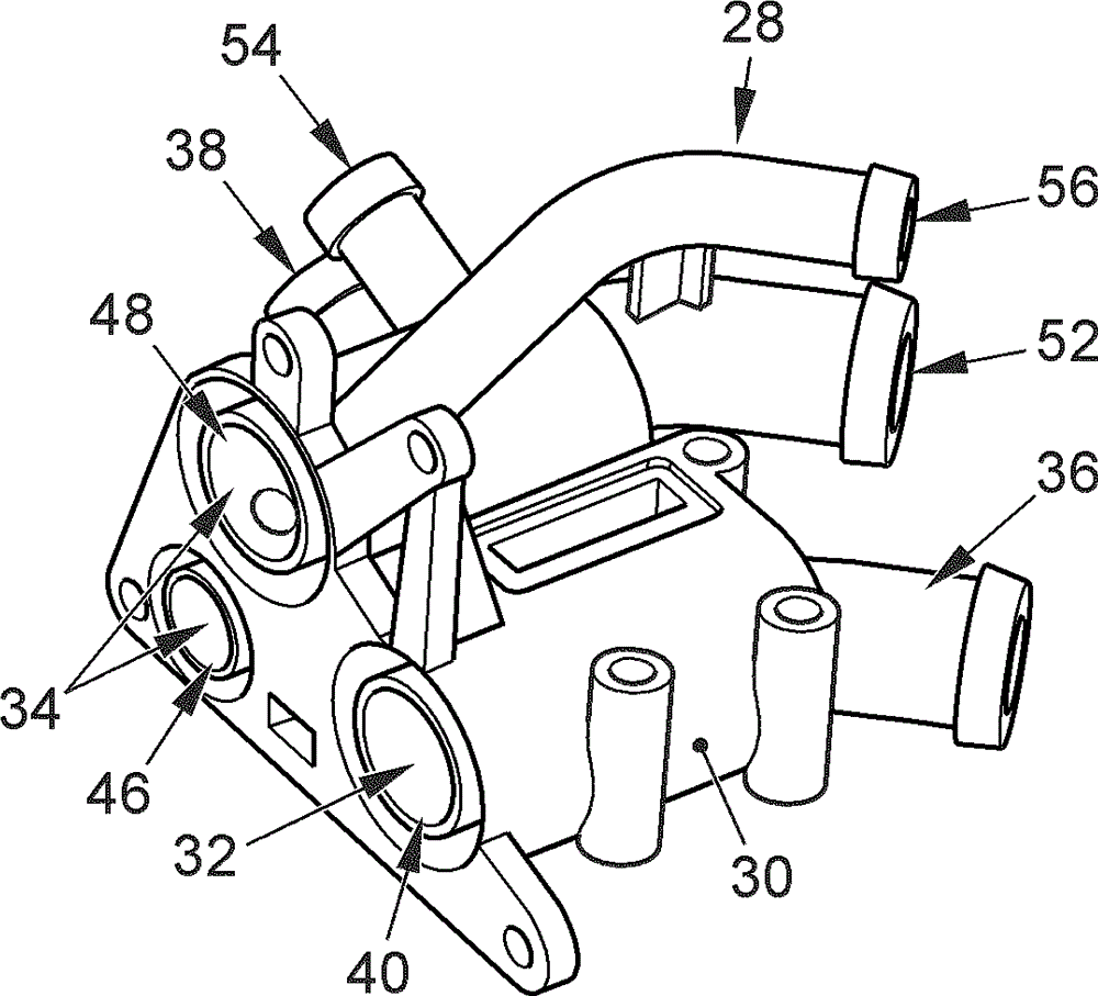
[0069] figure 1 Shown is an internal combustion engine with a cooling system according to the invention, the engine 10 of the internal combustion engine being shown in addition to the cooling system. The engine 10 can be embodied as a conventional piston reciprocating engine and then includes a cylinder crankcase 12 in which a plurality of cylinders (not shown) are formed, in which a piston (not shown) is each movably guided. The cylinder head 14 closes the cylinder crankcase 12 and thus closes the cylinders towards the top and furthermore comprises at least one intake valve and at least one exhaust valve for each cylinder, which are controlled in a known manner in the construction of cylinders and pistons. gas exchange in the combustion chamber.

[0070] Both the cylinder crankcase 12 and the cylinder head 14 are cooled by means of the cooling system, for which they have cooling channels 58 , 60 which are filled with the coolant of the cooling system and flow through it at l...


PUM


Abstract

The present invention relates to a cooling system which is used for an internal combustion engine and consists of a first cooling circulation comprising a component cooler, an environment heat exchanger and a pump (18) and a second cooling circulation comprising a component cooler and a pump (24), wherein the cooling circulations are integratedly configured in at least one section and coolant configured to be conveyed by the pumps (18, 24) is arranged in the cooling circulations, and the cooling system is characterized in that the pumps are adjustably configured and adjustment of volume flow of the coolant flowing through the component coolers can be realized through cooperated operation of the pumps (18, 24).

Description

technical field [0001] The invention relates to a cooling system for an internal combustion engine. Background technique [0002] An internal combustion engine for a motor vehicle has at least one cooling system, in which the coolant is pumped in at least one cooling circuit by means of one or more pumps and absorbs components integrated into the cooling circuit, in particular the engine and oil cooling. cooler and / or charge air cooler heat. This thermal energy is then emitted to the ambient air in ambient heat exchangers (Umgebungswaermetauscher), so-called main water coolers and sometimes in heating heat exchangers (Heizungswaermetauscher), in the case of heating heat exchangers to the devices provided for Air-conditioned ambient air in the interior of a motor vehicle. [0003] The cooling systems of modern motor vehicles usually have several cooling circuits. For example, it is known to provide a so-called major or main cooling circuit and a minor cooling circuit, whic...

Claims


Application Information

Patent Timeline
Patent Type & Authority Applications(China)
IPC IPC(8): F01P7/14F01P3/02F01P11/16F01P5/12
CPCF01P7/164F01P7/162F01P7/165F01P11/0204F01P11/029F01P2003/027F01P2005/105F01P2005/125F01P2007/146F01P2025/32F01P2025/33F01P2037/02F01P2060/04F01P2060/08F01P7/14F01P3/02F01P5/12F01P11/16F01P2050/16F01P2050/22F01P2050/24
Inventor C. 克普纳
Owner VOLKSWAGEN AG
Why Eureka
Try Eureka