Method and system of performing interference testing on aspheric surface optical element

An interference system and optical element technology, used in diffractive optical elements transmitted by test and reference beams multiple times, interference test field, can solve problems such as difficulty of test beam

Active Publication Date: 2015-05-27
帝麦克斯(苏州)医疗科技有限公司
View PDF5 Cites 7 Cited by
  • Summary
  • Abstract
  • Description
  • Claims
  • Application Information

AI Technical Summary

Problems solved by technology

However, to test an aspheric surface, it is difficult to generate a suitable test beam

Method used


Image

  • Method and system of performing interference testing on aspheric surface optical element
  • Method and system of performing interference testing on aspheric surface optical element
  • Method and system of performing interference testing on aspheric surface optical element

Examples


Embodiment

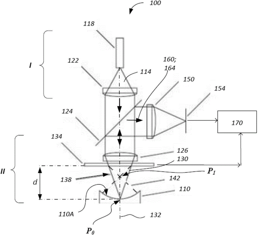
[0054] This embodiment provides a common path interference system, such as figure 1 As shown, the interference system is a single-arm interference system of the solution 100 of the present invention. To test an optical element 110 (eg, an aspheric lens) in the aspheric optical system 110A, a collimated beam 114 of wavelength λ from a coherent light source (in one approach—laser 118 ) will be used. The light beam 114 is collimated by using a collimating optical system 122 (which may include a lens or a plane mirror, for simplicity it is a collimating lens). During the collimation process, the light beam is further transmitted to a beam splitter 124 and a wavefront converging (for example, focusing) optical system 126 (simply speaking, a focusing lens), thereby forming a spatially focused light beam 130, which There is a spherical wavefront propagating along optical axis 132 . In the present invention, the space I in front of the collimating lens 122 is an object space, and th...


PUM


Abstract

The invention discloses a method and system of performing interference testing on an aspheric surface optical element. In reflection, a diffractive element horizontally arranged on an optical axis of a common path interferometer forms two diffraction beams (with different diffraction items). The first diffraction beam keeps a wave surface irradiating to the diffractive element; the second diffraction beam has a wave surface corresponding with a surface to be detected. The first diffraction beam can be reflected by a surface in a cat eye device; the second diffraction beam can be reflected by a surface of a confocal surface. The surface to be detected can be adjusted to balance the intensity of the first diffraction beam and the second diffraction beam reflected to the surfaces.

Description

technical field [0001] The invention relates to a method and system for interference testing of aspheric optical elements, in particular to a method for testing a diffractive optical element with co-path interference and transmitted multiple times by test and reference beams, belonging to the field of optoelectronic technology. Background technique [0002] Laser interferometers are often used to measure the surface shape of high-precision optical components. This test method uses a reference beam (usually with a normally spherical wavefront) to interfere with a test beam (usually with a wavefront that matches the surface being tested). In order to characterize a spherical system under test or an irregular planar system under test, the wavefront of the test beam can be easily generated. However, generating a suitable test beam for testing an aspheric surface is difficult. One method used to generate a test beam to characterize an aspheric or random system under test is to ...

Claims


Application Information

Patent Timeline
Patent Type & Authority Applications(China)
IPC IPC(8): G01B11/24G01B9/02
CPCG01B9/02057G01M11/0271G01B9/021G01B11/2441G01B9/02039G01M11/02G01B9/02015G01B11/30
Inventor 梁晨周丕轩
Owner 帝麦克斯(苏州)医疗科技有限公司
Why Eureka
Try Eureka