
A main loop circulation device for a pool-type liquid heavy metal cooling reactor

A liquid heavy metal and reactor technology, applied in cooling devices, reactors, reducing greenhouse gases, etc., can solve problems such as low economy, large space inside the reactor, and coolant retention, and achieve the effect of improving economy and simple system structure.

Active Publication Date: 2017-03-01
HEFEI INSTITUTES OF PHYSICAL SCIENCE - CHINESE ACAD OF SCI
View PDF4 Cites 0 Cited by
  • Summary
  • Abstract
  • Description
  • Claims
  • Application Information

AI Technical Summary

Problems solved by technology

[0003] The first one is the shutting down method of dropping rods in the China Advanced Research Reactor CARR. The coolant flows downward through the core under normal operating conditions, and turns to flow upward through the core under natural circulation under accident conditions. Depending on the inertial coolant, the downward flow can still be maintained for a period of time, and the rod drop time can be guaranteed, but the coolant in the core remains for a period of time under accident conditions, and there may be a risk of cladding fusion
[0004] The second is the European ALFRED shutdown method in which the counterweight drops the rods downward. Due to the resistance of the upward flow of the coolant in the core, the rod drop time is greatly affected by the flow rate of the coolant in the core, and it is difficult to fully guarantee it.
Refueling needs to be opened, which affects the safety of the reactor
[0005] The third is the shutdown method of European MYRRHA which adopts buoyancy to lift the rod upwards. The shutdown time of this scheme can be guaranteed. The reactor core needs to be arranged in the upper space of the container, which requires a large reactor space and increases the amount of coolant, which is economical. The performance of the reactor is not high, and at the same time, the large amount of coolant reduces the seismic performance of the reactor, and there are certain safety hazards

Method used


Image

  • A main loop circulation device for a pool-type liquid heavy metal cooling reactor

Examples


Embodiment Construction

[0015] Below in conjunction with accompanying drawing and specific embodiment the present invention is described in further detail:

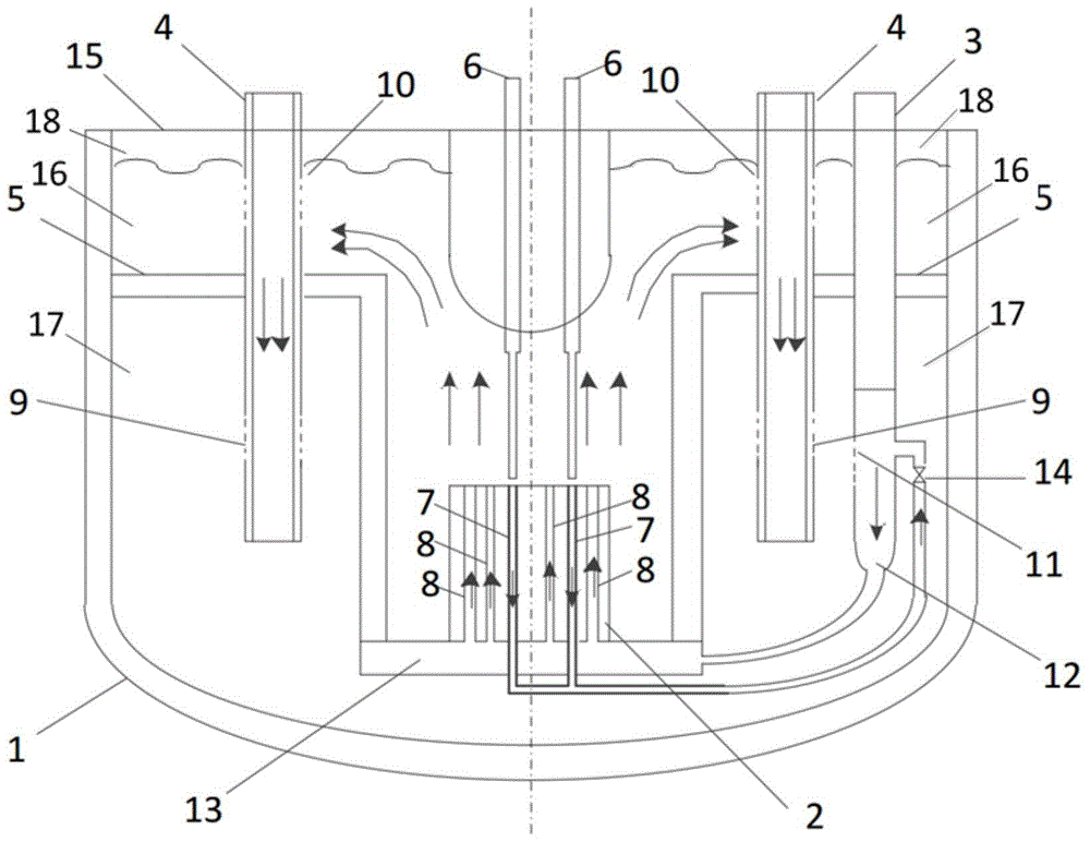
[0016] Such as figure 1 As shown, the present invention is a kind of main circuit circulation device for pool type liquid heavy metal cooling reactor, including container 1, reactor core 2, main pump 3, heat exchanger 4, thermal partition 5, control rod driving mechanism 6, control Rod assembly 7, fuel assembly 8, heat exchanger outlet 9, heat exchanger inlet 10, main pump inlet 11, main pump outlet 12, grid header 13, throttle valve 14, stack top cover 15, Hot pool 16, cold pool 17, cover gas 18; grid header 13 is used to support core 2, thermal partition 5 fixes grid header 13 at the bottom of container 1, and thermal partition 5 connects main circuit coolant It is divided into two parts, the upper hot pool 16 and the lower cold pool 17. Covering gas 18 is filled between the stack roof 15 and the hot pool 16. The control rod assembly 7 and th...


PUM


Abstract

The invention discloses a main loop circulating device for a pool type liquid heavy metal cooling reactor. The main loop circulating device comprises a container, a reactor core, a main pump, a heat exchanger, a thermal baffle, a control rod driving mechanism, a control rod assembly, a fuel assembly, a heat exchanger outlet end, a heat exchanger inlet end, a main pump inlet end, a main pump outlet end, a grid plate header, a throttling valve, a reactor top cover, a hot pool, a cold pool and cover gas. According to the main loop circulating device disclosed by the invention, the rod dropping time of the control rod driving mechanism can be effectively guaranteed under accident conditions, the structure of the device is simple, only a set of pipeline system needs to be additionally arranged in the main container, the operations of running, refueling and shutting down the reactor are not influenced, and the economical efficiency, reliability and safety of the reactor are effectively improved.

Description

technical field [0001] The invention relates to a reactor main loop circulating device technology, in particular to a main loop circulating device for a pool-type liquid heavy metal cooling reactor. Background technique [0002] In liquid heavy metal cooled reactors, there are mainly the following shutdown methods under accident conditions: [0003] The first one is the shutting down method of dropping rods in the China Advanced Research Reactor CARR. The coolant flows downward through the core under normal operating conditions, and turns to flow upward through the core under natural circulation under accident conditions. Relying on the inertial coolant, the downward flow can still be maintained for a period of time, and the time for rod drop can be guaranteed. However, under accident conditions, the coolant in the core remains for a period of time, and there may be a risk of cladding fusion. [0004] The second is the European ALFRED shutdown method in which the counterwei...

Claims


Application Information

Patent Timeline
Patent Type & Authority Patents(China)
IPC IPC(8): G21C15/02G21C15/14G21C15/22
CPCG21C15/02G21C15/14G21C15/22Y02E30/30
Inventor 刘书勇周涛柏云清宋勇吴宜灿
Owner HEFEI INSTITUTES OF PHYSICAL SCIENCE - CHINESE ACAD OF SCI
Learn More