
Patsnap Eureka
For R&D, Patsnap Eureka makes reading and utilizing patents & technical documents easy.
Patsnap Eureka AIR
Designed for self-driven R&D workflows. Generate viable solutions, solve complex R&D challenges, empower your innovation with AI.

Patsnap Eureka Materials
Designed for material experts only. Revolutionize your material R&D, from search, analyze, to developing new materials.

TechResearch
Generate reliable direction feasibility study reports for your R&D in just a few steps.

TechSeek
Discover and master advanced knowledge NOW. Basics, ideas, possibilities, all at once.

TechMind
As an expert in R&D Theories, TechMind can generates customized viable solutions instantly.

TechRisk
Analyze your overall solution with one click, know your potential R&D risks in advance.

TechMonitor
Get weekly tech updates, stay abreast of the latest tech innovations and key insights.
Resonator element, resonator, oscillator, electronic device, and mobile object
A vibrating piece and oscillator technology, which is applied in the fields of vibrating piece, vibrator, electronic equipment, moving body and oscillator, can solve the problems of complicated manufacturing process, decreased product reliability, tilt and so on.
- Summary
- Abstract
- Description
- Claims
- Application Information
AI Technical Summary
Problems solved by technology
Method used
Image

Examples
no. 1 Embodiment approach >
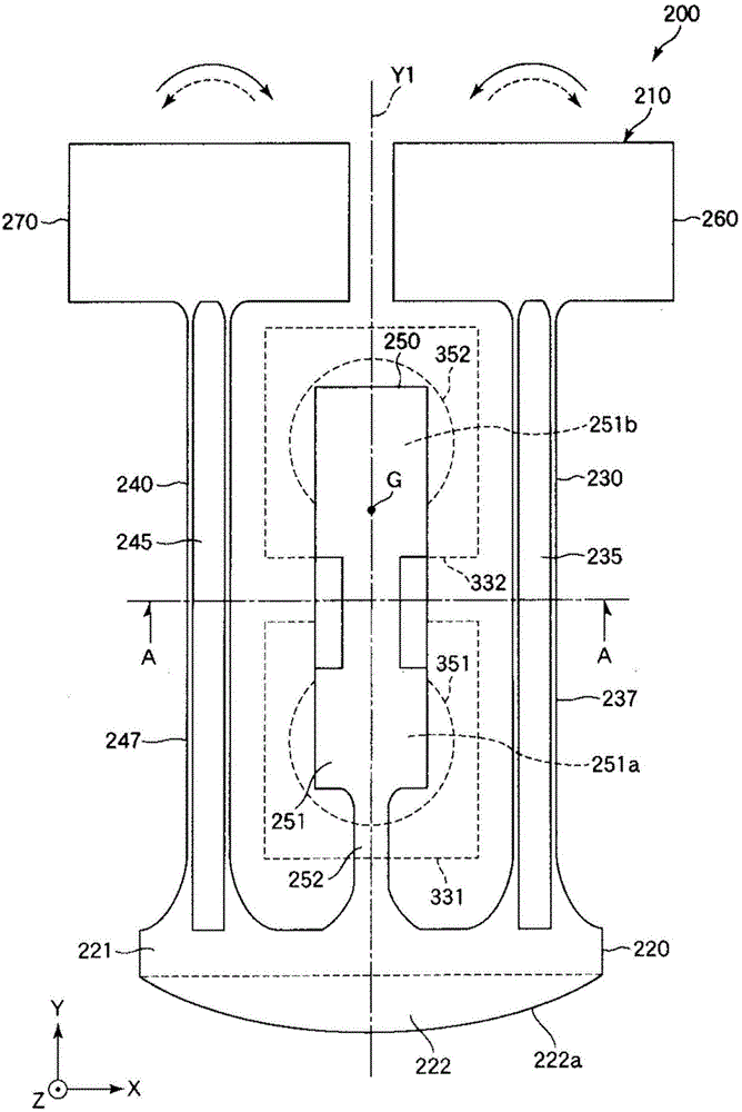
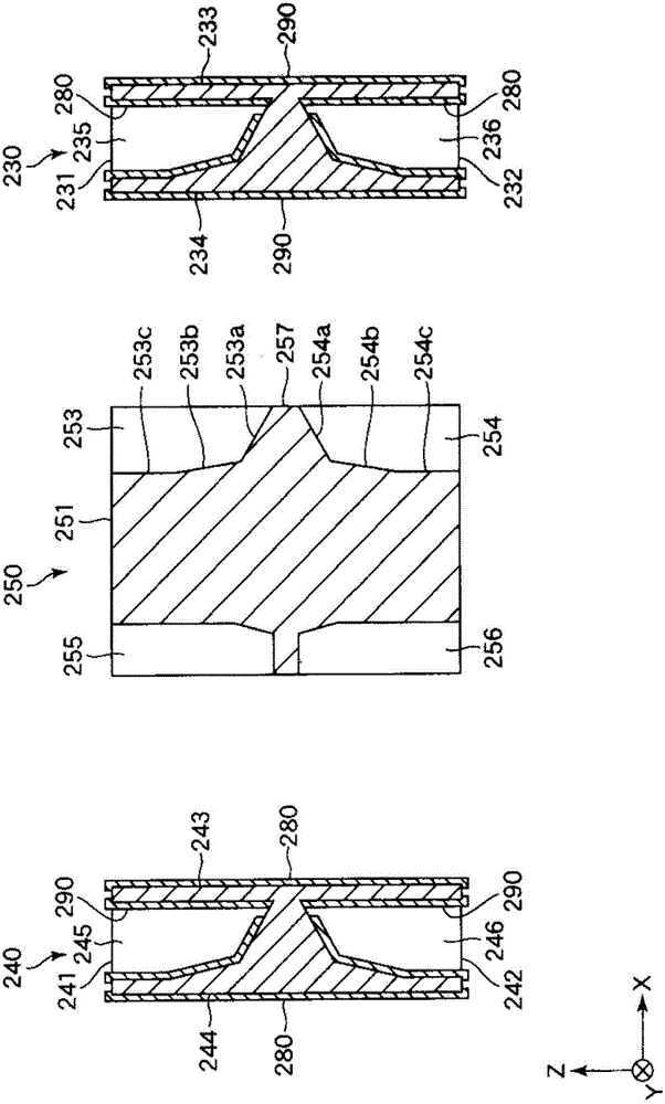
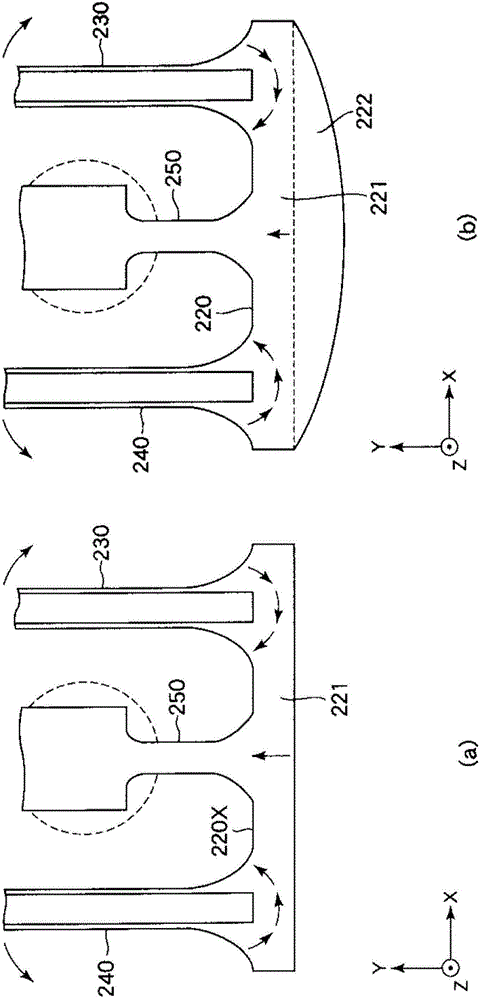
[0052] figure 1 It is a plan view showing the vibrating piece according to the first embodiment of the present invention, figure 2 yes figure 1 The A-A line sectional view in. also, image 3 It is a plan view explaining the principle of vibration leakage suppression.
[0053] In addition, in each figure, for convenience of description, the X-axis, the Y-axis, and the Z-axis are illustrated as three axes perpendicular to each other. In addition, in the following description, the direction parallel to the X-axis (second direction) is referred to as the "X-axis direction", the direction parallel to the Y-axis (first direction) is referred to as the "Y-axis direction", and The direction (third direction) parallel to the Z-axis is referred to as the "Z-axis direction", and the end sides of the arrows of the X-axis, Y-axis, and Z-axis shown in each figure are referred to as "+ (positive)", and The base end side is referred to as "- (minus)". In addition, in the following desc...
no. 2 Embodiment approach >
[0118] Next, a second embodiment of the present invention will be described.
[0119] Figure 7 It is a plan view showing the vibrating piece according to the second embodiment of the present invention.
[0120] Hereinafter, regarding the second embodiment, differences from the above-described embodiment will be mainly described, and descriptions of the same matters will be omitted.
[0121] The second embodiment is substantially the same as the first embodiment except that the structure (shape) of the narrowed portion of the base is different. exist Figure 7 In , the same reference numerals are assigned to the same structures as those in the above-mentioned embodiment.
[0122] Figure 7 The base portion 220A included in the vibrating piece 200A shown has a reduced width portion 222A. The outline of the reduced-width portion 222A is constituted by linear inclined portions 222 b and 222 c inclined with respect to two axes, the X axis and the Y axis, in plan view. One en...
PUM
 Abstract
Description
Claims
Application Information
 - R&D Engineer
- R&D Manager
- IP Professional
- Industry Leading Data Capabilities
- Powerful AI technology
- Patent DNA Extraction
Browse by: Latest US Patents, China's latest patents, Technical Efficacy Thesaurus, Application Domain, Technology Topic, Popular Technical Reports.
© 2024 PatSnap. All rights reserved.Legal|Privacy policy|Modern Slavery Act Transparency Statement|Sitemap|About US| Contact US: help@patsnap.com