
Signal processing for a capacitive sensor system with robustness to noise

A capacitive sensor, sensor technology, applied in signal processing. Field, can solve the problem of electric noise source affecting the electric field and so on

Active Publication Date: 2015-05-27
MICROCHIP TECH GERMANY II
View PDF5 Cites 5 Cited by
  • Summary
  • Abstract
  • Description
  • Claims
  • Application Information

AI Technical Summary

Problems solved by technology

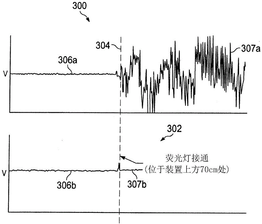
[0005] The problem with conventional systems operating on the above principle is that sources of electrical noise (such as fluorescent lights or USB chargers) can affect the electric field
Therefore, accurate and reliable estimation of this voltage in noisy environments is problematic

Method used


Image

  • Signal processing for a capacitive sensor system with robustness to noise
  • Signal processing for a capacitive sensor system with robustness to noise
  • Signal processing for a capacitive sensor system with robustness to noise

Examples


Embodiment Construction

[0023] The invention and its various features and advantageous details can be more fully explained with reference to the exemplary and therefore non-limiting embodiments illustrated in the accompanying drawings and detailed in the following description. It should be understood, however, that the detailed description and specific examples, while indicating preferred embodiments, are illustrative only and not restrictive. Descriptions of well-known programming techniques, computer software, hardware, operating platforms and protocols may be omitted so as not to unnecessarily obscure the present invention in detail. Various substitutions, modifications, additions and / or rearrangements within the spirit and / or scope of the basic inventive concept will be apparent to those skilled in the art from this disclosure.

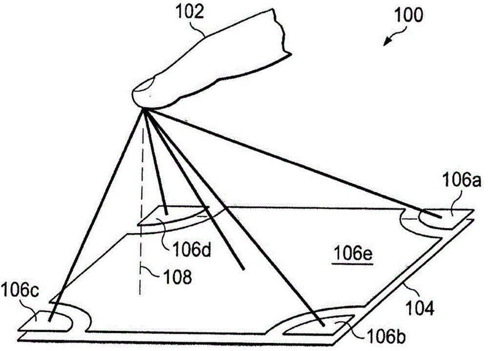
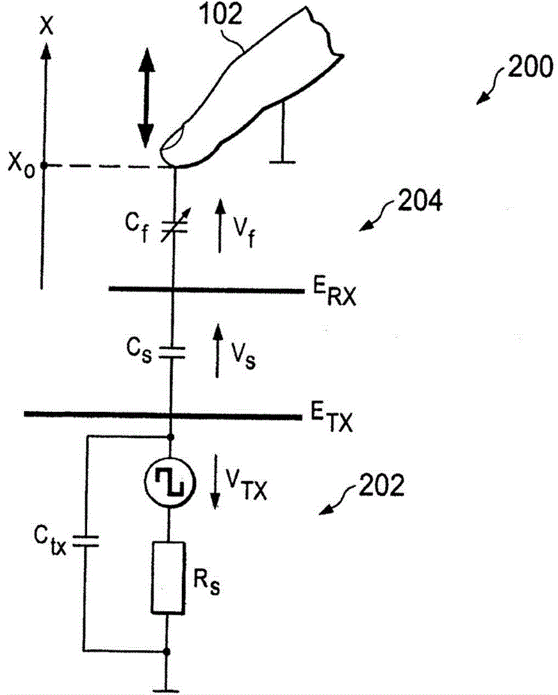
[0024] Turning now to the schema and paying particular attention to figure 1 , an exemplary sensor electrode arrangement 100 for estimating an alternating electric fie...


PUM


Abstract

A capacitive sensor includes a transmit electrode configured to provide an alternating electric field to a sensor; one or more receive electrodes for detecting variations in the alternating electric field; and an adaptive frequency adjustment unit configured to adjust an operating frequency of the alternating electric field responsive to detection of a noise measure, such as noise power.

Description

[0001] Cross References to Related Applications [0002] This application claims priority to US Provisional Patent Application No. 61 / 684,009, filed August 16, 2012, which is hereby incorporated by reference in its entirety as if fully set forth herein. technical field [0003] The present invention relates to methods and systems for capacitive sensor systems, and in particular to signal processing in such systems. Background technique [0004] A capacitive sensor system can be realized by generating an alternating electric field and measuring the potential difference (ie, voltage) obtained in one cycle at the sensor electrodes within this electric field. A single electrode or a transmit electrode and one or more receive electrodes may be used. This voltage is a measure of the capacitance between the sensor electrode and its electrical environment, ie it is affected by an object such as a person's finger or hand. Furthermore, for example, the distance of the finger can be...

Claims


Application Information

Patent Timeline
IPC IPC(8): G01D5/24H03K17/96G06F3/044
CPCG01D5/24H03K17/962H03K2217/9607G06F3/0445G01R31/005G01R27/2605G01R35/005H03M1/001
Inventor 阿克塞尔·海姆马丁·霍赫
Owner MICROCHIP TECH GERMANY II
Learn More