A double-brake back-and-forth controllable descending device

A technology of double brakes and descenders, which is used in building rescue, life-saving equipment, etc., can solve the problems of inability to use elevators, few descenders, and inconvenience to carry, and achieves strong controllability and avoids loss or offset. , to ensure the effect of high precision requirements

Active Publication Date: 2017-07-18
嘉善罗星创业投资有限公司
View PDF4 Cites 1 Cited by
  • Summary
  • Abstract
  • Description
  • Claims
  • Application Information

AI Technical Summary

Problems solved by technology

[0002] There are more and more existing high-rise buildings, how to safely escape from high-rise buildings when encountering fires, earthquakes or sightseeing cable car mechanism accidents and hanging in the air is an urgent problem in the world today. A big problem is that the height of the fire-fighting ladder is limited, and the elevator cannot be used in case of a disaster
Various descending devices have been developed in the industry for escape from high-rise buildings. However, the existing descending devices have the following problems: (1) heavy and bulky, and inconvenient to carry; (2) unable to slow down and brake in the air Hovering; (3) The state and speed of descent cannot be controlled; (3) High-speed friction has a great impact on the loss of internal components, which constitutes a safety hazard
[0003] Due to the above defects, considering safety reasons, there are few practical applications of descending devices in reality. In order to solve the above technical problems, it is urgent to provide a descending device with high safety factor, strong controllability, practical and convenient

Method used


Image

  • A double-brake back-and-forth controllable descending device
  • A double-brake back-and-forth controllable descending device
  • A double-brake back-and-forth controllable descending device

Examples


Embodiment Construction

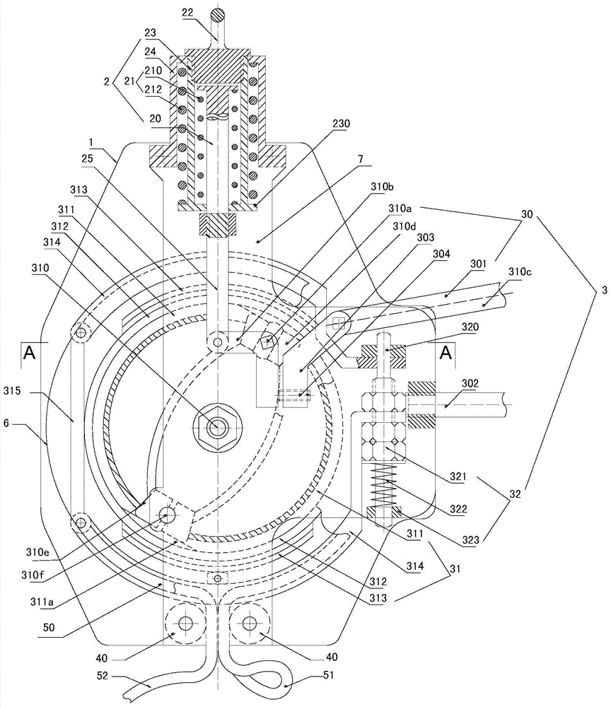
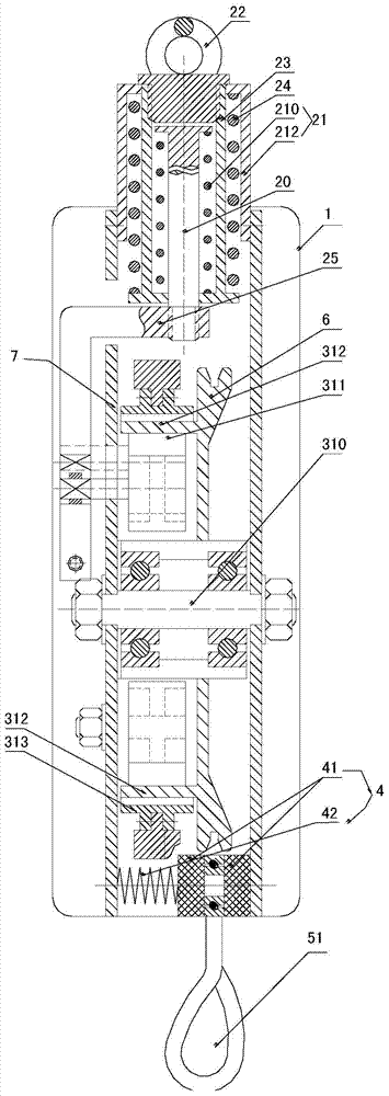
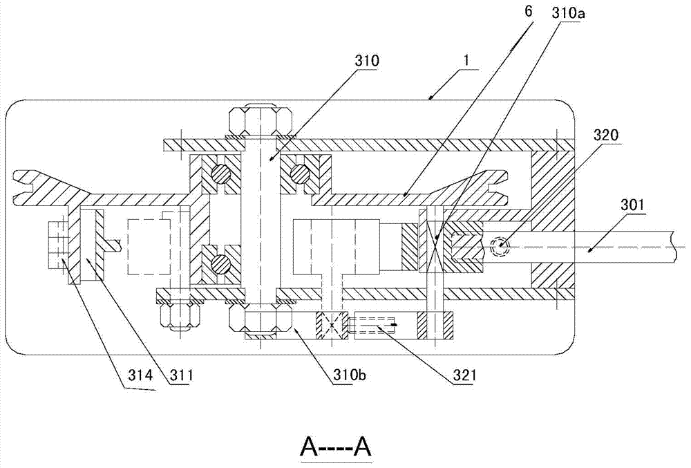
[0041] refer to Figure 1 to Figure 3 As shown, the present invention provides a dual-brake back-and-forth controllable descent device 100, which includes an outer shell 1 and a lifting mechanism 2 built in it, a double-braking mechanism 3, a rope guide mechanism 4 and a wedge wheel 6 , the pulling mechanism 2 is linked with the double brake mechanism 3, the pulling mechanism 2 includes an energy conversion adjustment screw 20 and a buffer member 21 arranged on its outer periphery, and the double brake mechanism 3 includes an outer brake assembly 30. An inner brake assembly 31 and a self-locking mechanism 32. The inner brake assembly 31 is linked with the energy conversion adjustment screw 20 of the lifting mechanism 2. The outer circumference of the inner brake assembly 31 is provided with a wedge wheel 6. A wire rope 50 is wound on the wedge wheel 6, and the self-locking mechanism 32 can be movably resisted between the outer brake assembly 30 and the outer casing 1. In this...


PUM


Abstract

The invention discloses a double-brake back-and-forth controllable descent control device. The double-brake back-and-forth controllable descent control device comprises an outer shell, a pulling mechanism, a double-brake mechanism and a rope guiding mechanism, wherein the pulling mechanism, the double-brake mechanism and the rope guiding mechanism are arranged in the outer shell; the pulling mechanism is mutually linked with the double-brake mechanism and comprises an energy conversion regulating screw rod and a buffer piece which is arranged at the periphery of the pulling mechanism; the double-brake mechanism comprises an outer brake assembly, an inner brake assembly and a self locking mechanism, the inner brake assembly is mutually linked with the energy conversion regulating screw rod of the pulling mechanism, a wedge wheel is arranged at the periphery of the inner brake assembly, a steel wire rope is wound on the wedge wheel and is in rolling friction, and the self locking mechanism is movably arranged between the outer brake assembly and the outer shell in a leaning way; when the outer brake assembly is in an unstressed state or a maximum stress state, the inner brake assembly is in a semi-brake state to generate friction damping, and the steel wire rope wound on the peripheral wedge wheel can be tensioned and locked; when the outer brake assembly is in a semi-clutch state, the inner brake assembly and a brake hub are in a friction state by the locking of the inner brake assembly on the steel wire rope, the steel wire rope is enabled to be guided out along the rope guiding mechanism by friction force difference, and slow and uniform-speed descending can be realized.

Description

technical field [0001] The invention relates to a descending device, in particular to a double-brake back-and-forth controllable descending device which can realize self-rescue, other rescue and air braking. Background technique [0002] There are more and more existing high-rise buildings, how to safely escape from high-rise buildings when encountering fires, earthquakes or sightseeing cable car mechanism accidents and hanging in the air is an urgent problem in the world today. One big problem is that the height that the fire-fighting aerial ladder can extend is limited, and the elevator cannot be used in case of a disaster. Various descending devices have been developed in the industry for escape from high-rise buildings. However, the existing descending devices have the following problems: (1) heavy and bulky, and inconvenient to carry; (2) unable to slow down and brake in the air Hovering; (3) The state and speed of descent cannot be controlled; (3) High-speed friction ...

Claims


Application Information

Patent Timeline
Patent Type & Authority Patents(China)
IPC IPC(8): A62B1/14
CPCA62B1/10
Inventor 李宗荣黄柏源
Owner 嘉善罗星创业投资有限公司
Why Eureka
Try Eureka