
Automatic loading/unloading equipment

An automatic loading and unloading and equipment technology, applied in the field of mechanical equipment, can solve the problem of no clamping force adjustment method, and achieve the effect of avoiding deformation

Inactive Publication Date: 2015-06-03
沈阳金刚工业自动化有限公司
View PDF6 Cites 12 Cited by
  • Summary
  • Abstract
  • Description
  • Claims
  • Application Information

AI Technical Summary

Problems solved by technology

There are many similar patents, all of which basically use motor drive to adjust the three-dimensional space, but few patents disclose the structure of the clamping part, and even if there are individual disclosures, there is no method for adjusting the clamping force. Therefore, there is an urgent need An automatic loading and unloading device that can automatically perform position positioning and clamping force setting

Method used


Image

  • Automatic loading/unloading equipment
  • Automatic loading/unloading equipment
  • Automatic loading/unloading equipment

Examples


Embodiment Construction

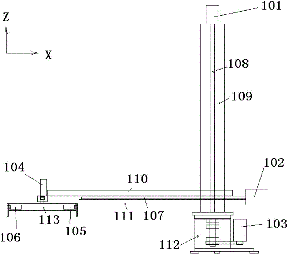
[0021] The present invention is specifically described below in conjunction with accompanying drawing, as figure 1 As shown, the present invention includes a longitudinal driving device, a horizontal driving device, a rotating device and a clamping part; the clamping part is provided with a material rotating device;

[0022] Described longitudinal driving device comprises the motor one 101 that is arranged on the vertical frame upper end, and described motor one 101 drives lead screw one 108 to rotate, and leading screw one 108 cooperates with the fixed portion of transverse drive device to ensure that transverse drive device can move along the longitudinal frame. 109 move up and down;

[0023] The horizontal driving device includes a motor 2 102, and the motor 2 102 drives a screw 2 107, and the screw 2 107 drives the clamping part to move left and right between the horizontal frames 110 and 111;

[0024] The rotating device includes a motor three 103, and the three motors 1...


PUM


Abstract

The invention discloses automatic loading / unloading equipment. The automatic loading / unloading equipment comprises a vertical driving device, a transverse driving device, a rotary device and a clamping part, wherein the clamping part is provided with a material rotary device; the vertical driving device comprises a motor I which is arranged at the upper end of a vertical rack; the motor I drives a screw rod I to rotate; the screw rod I is matched with a fixed part of the transverse driving device to guarantee that the transverse driving device can move up and down along the vertical rack; the transverse driving device comprises a motor II; the motor II drives a screw rod II; the screw rod II drives the clamping part to move left and right on a transverse rack; the rotary device comprises a motor III; the motor III drives the vertical rack by a gear to rotate horizontally; the material rotary device comprises a motor IV; the motor IV drives the clamping part to rotate. The automatic loading / unloading equipment has the advantages that the high automation is realized; the clamping force can be pre-set and different technical requirements are adapted; workpieces are not damaged in a loading / unloading process.

Description

technical field [0001] The invention relates to the field of mechanical equipment, in particular to a loading and unloading equipment. Background technique [0002] There are many kinds of existing automatic loading and unloading equipment. For example, Chinese patent application No. 94115658.3 discloses a loading and unloading equipment, which has at least one telescopic cylinder with retractable and extended telescopic parts, which is used for loading and unloading objects, especially wrapping packaging materials. The reels, working together with the packaging machinery, can use several long-stroke telescoping members, which are used to generate the automatic movement of the carrying pins holding the reel. The tension member is placed outside the telescopic member, one end of which is fixed and anchored, and the other end can be wound up and released. The tension member passes through a steering wheel, and the steering wheel is placed on the free end of the telescopic memb...

Claims


Application Information

Patent Timeline
IPC IPC(8): B65G47/90
Inventor 王永升张琪
Owner 沈阳金刚工业自动化有限公司
Learn More