Skid wire connection box

A connection box and sliding wire technology, applied in the direction of connection, current collectors, electrical components, etc., can solve the problems of low efficiency, long time consumption of sliding wire connection box, etc., to reduce maintenance cost, reduce maintenance time, installation/removal Fast and easy process

Inactive Publication Date: 2015-06-03
宝钢日铁汽车板有限公司
View PDF4 Cites 6 Cited by
  • Summary
  • Abstract
  • Description
  • Claims
  • Application Information

AI Technical Summary

Problems solved by technology

[0008] The purpose of the present invention is to provide a sliding wire connection box, which effectively solves the problems of long time consumption and low efficiency in installing and disassembling the sliding wire connecting box, and can check the sliding wire connection without disassembling the sliding wire connecting box At the same time, it abandons the existing connection method, thus avoiding the safety hazard caused by the bolt falling from high altitude

Method used


Image

  • Skid wire connection box
  • Skid wire connection box
  • Skid wire connection box

Examples


Embodiment Construction

[0036] The following will further explain and illustrate the sliding wire connection box of the present invention in conjunction with the accompanying drawings and specific embodiments, but such explanations and illustrations do not constitute undue limitations on the technical solution of the present invention.

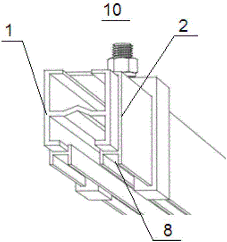
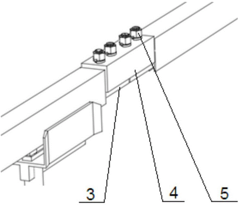
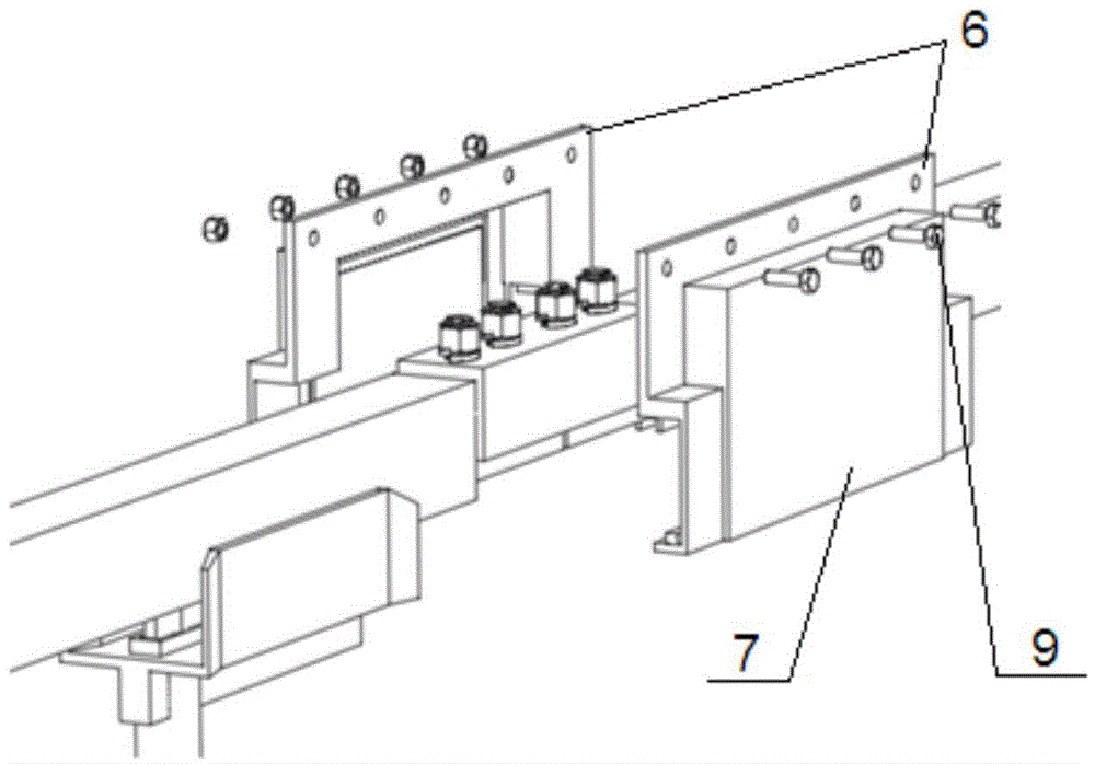
[0037] Figure 4 shows the structure of the sliding wire connection box in an embodiment of the present invention, and Figure 5 then shows Figure 4 The structure of the slider junction box body in the slider junction box shown.

[0038] Such as Figure 4 and Figure 5 As shown, the sliding wire connection box 20 includes two connection box split bodies 21 and two end locking frames 22, and the two connection box split bodies 21 are hingedly connected at one length edge of the two, thereby forming a sliding wire that can be opened and closed. The wire connection box body 25 has a cavity 23 for accommodating the slide wire in the wire connection box, and observat...


PUM


Abstract

The present invention discloses a skid wire connection box, which comprises: two connection box splitting bodies, wherein the two connection box splitting bodies are hinged at one length edge so as to form the skid wire connection box body capable of being opened and closed, a cavity for holding a skid wire is arranged inside the skid wire connection box, and at least one of the two connection box splitting bodies is provided with an observation window; and at least an end portion locking frame, wherein the end portion of the skid wire connection box body at the length direction is sleeved in the skin wire connection box under the use state of the end portion locking frame. According to the present invention, the skid wire connection box has characteristics of simple structure, easy manufacturing, low cost and easy installation; the skid wire connection box can be quickly installed and removed, and the existing bolt/screw connection is discarded, such that the safety hidden danger of the high-altitude bolt/screw falling is avoided, and the skid wire movement and the connection plate bolt loosing can be effectively checked without removal of the skid wire connection box so as to improve the maintenance efficiency of the bridge crane.

Description

technical field [0001] The invention relates to a connection device, in particular to a connection device for sliding wires. Background technique [0002] The power used by the bridge crane comes from the slide wire installed on the supporting rail beam, and the slide wire transmits power to the crane through the collector shoe installed on the crane. Such as figure 1 As shown, the sliding wire body 10 is composed of a conductive part 1 of copper alloy material and a shell 2 of plastic insulating material. Conducting electricity during the contact sliding process of the sliding contact line, the bottom of the shell 2 is provided with a groove 8 of a certain depth, which is used as a connection box for installation. Such as figure 2 As shown, the sliding wire is connected by several sliding contact wires through the connecting device, and the two sliding contact wires 3 are connected by bolts 5 through the connecting plate 4 of the sliding contact wire. The connecting pla...

Claims


Application Information

Patent Timeline
Patent Type & Authority Applications(China)
IPC IPC(8): B66C13/12H01R41/00
CPCB66C13/12H01R41/00
Inventor 顾希成陈华
Owner 宝钢日铁汽车板有限公司
Why Eureka
Try Eureka