Gas sealing device and method for soaking zone of continuous annealing furnace

A technology of continuous annealing furnace and soaking section, which is used in furnaces, heat treatment furnaces, furnace types, etc., can solve the problems that the furnace pressure cannot be kept stable in the soaking section, and the rise of hot air flow cannot be effectively restricted, so as to prevent the hot air flow. rising effect

Active Publication Date: 2015-06-03
武汉钢铁有限公司
View PDF4 Cites 2 Cited by
  • Summary
  • Abstract
  • Description
  • Claims
  • Application Information

AI Technical Summary

Problems solved by technology

From the point of view of actual use, the sealing flap cannot effectively limit the rise of the hot air flow, nor can it keep the furnace pressure in the soaking section stable.

Method used


Image

  • Gas sealing device and method for soaking zone of continuous annealing furnace

Examples


Embodiment Construction

[0012] In order to better understand the present invention, the present invention will be further described below in conjunction with the accompanying drawings and embodiments.

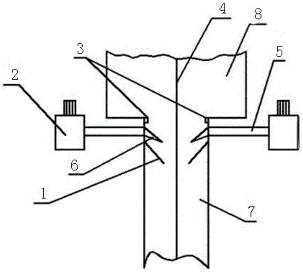
[0013] It includes two baffles 1 symmetrically arranged on the inner wall of the exit of the soaking section 7 of the continuous annealing furnace. The top of the top is connected to the inner wall at the outlet of the soaking section, and the inner wall above the top is respectively provided with an air supply port. The inner side of the air supply port is connected with a nozzle 6, and its outer side is connected with one end of the air supply pipe 5. The other end of the air supply pipe 5 A fan 2 is connected, and an infrared thermometer 3 is arranged on the inner wall above the nozzle 6 .

[0014] The distance between the bottoms of the two baffles 1 is 150mm-250mm, the nozzle 6 is a straight nozzle, the vertical distance between the outer edge of the nozzle and the baffle is 200mm-300mm, and the ...


PUM


Abstract

The invention provides a gas sealing device and a gas sealing method for a soaking zone of a continuous annealing furnace. The gas sealing device comprises two baffles which are symmetrically arranged on an inner wall at an outlet of the soaking zone of the continuous annealing furnace, wherein the two baffles are downwardly inclined and are arranged inside the soaking zone to be V-shaped; an air supply opening is formed in the inner wall above the top of each baffle; the inner side of each air supply opening is connected with a nozzle, and the outer side of each air supply opening is connected with one end of an air supply pipe; the other end of each air supply pipe is connected with a fan; an infrared thermometer is arranged on the inner wall above each nozzle. According to the gas sealing device and the gas sealing method for the soaking zone of the continuous annealing furnace, rising of the hot air of the soaking zone can be effectively prevented, the alloying process of a galvanized steel strip is not affected, and the surface quality of the galvanized steel strip is improved.

Description

technical field [0001] The invention belongs to the technical field of continuous annealing furnaces, and in particular relates to an air sealing device and method for a soaking section of a continuous annealing furnace. Background technique [0002] After the strip steel is hot-dip galvanized, it enters the continuous annealing furnace, which is usually designed as a vertical annealing furnace in order to save space. The galvanized steel strip enters the heating section and the soaking section in turn to complete the recrystallization and refinement of zinc particles. Due to the chimney effect of the air, the hot air in the soaking section will enter the cooling section along the pipeline. At present, the cold rolling mill equipment adopts a flap-type sealing device at the outlet of the hot-dip galvanizing soaking section to limit the temperature of the soaking section. The hot gas rises to the cooling section. From the point of view of actual use, the sealing flap cannot ...

Claims


Application Information

Patent Timeline
Patent Type & Authority Applications(China)
IPC IPC(8): C21D9/56C21D1/26
CPCC21D1/26C21D9/56
Inventor 邱碧涛严开勇万险峰陈刚胡念慈王玮李恒山
Owner 武汉钢铁有限公司
Why Eureka
Try Eureka