
Decelerating clutch of full-automatic washing machine

A technology for fully automatic washing machines and deceleration clutches, which is applied to other washing machines, washing machines with containers, washing devices, etc., and can solve the problems of reducing the rated capacity of washing and dehydration of washing machines, the difficulty of reducing the overall size of deceleration clutches, and reducing the volume of the outer tub of washing machines, etc. , to achieve the effect of simple and reliable structure, compact structure and increased height

Active Publication Date: 2015-06-03
QINGDAO HAIER WASHING MASCH CO LTD
View PDF6 Cites 17 Cited by
  • Summary
  • Abstract
  • Description
  • Claims
  • Application Information

AI Technical Summary

Problems solved by technology

[0006] The above-mentioned deceleration clutch adopting the transmission structure of the planetary fixed shaft gear train has a complex structure, increased loss, and reduced energy efficiency.

Method used


Image

  • Decelerating clutch of full-automatic washing machine
  • Decelerating clutch of full-automatic washing machine
  • Decelerating clutch of full-automatic washing machine

Examples


Embodiment 1

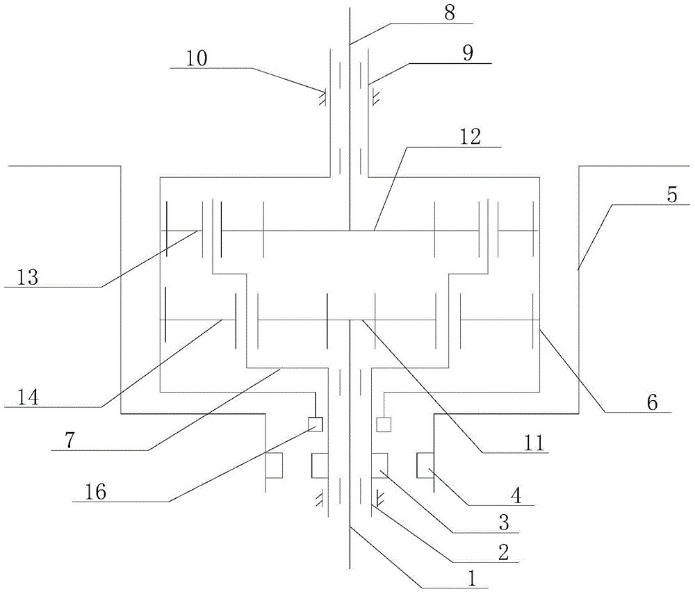
[0041] Such as Figure 1 to Figure 5 As shown, the deceleration clutch of the washing machine according to the present invention is mainly composed of an input shaft 1, an input shaft sleeve 2, an output shaft 8, an output shaft sleeve 9, a clutch mechanism, a housing 5 and a planetary gear train installed inside the gear train housing 5 . Planetary gear train is made up of mechanism such as input shaft gear 11, output shaft gear 12, a plurality of upper planetary gears 13, a plurality of lower planetary gears 14, planetary gear carrier 7, internal gear 6. The planetary gear train of the present invention is not only a deceleration transmission chain between the input shaft 1 and the output shaft sleeve 9, but also a transmission chain between the output shaft sleeve 9 and the output shaft 8 with deceleration and opposite directions.

[0042] The input shaft 1, the input shaft sleeve 2, the output shaft 8 and the output shaft sleeve 9 are all arranged coaxially, the input sha...

Embodiment 2

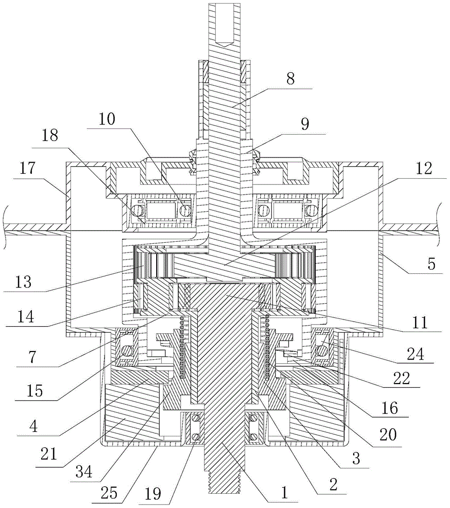
[0047] Such as Figure 2 to Figure 5 As shown, the clutch mechanism of the present invention includes a dehydration disc 16 mounted on the lower end of the internal gear 6, a clutch sleeve 3 mounted on the input shaft sleeve 2 and rotating integrally with the input shaft sleeve, and a brake disc 4 mounted on the casing 5. And driving the clutch cover 3 to slide up and down with the dehydration disc 16, the brake disc 4, the drive unit 21 and the clutch return spring 20, wherein the clutch return spring 20 is an extension spring, which is arranged between the planetary wheel carrier 7 and the clutch cover 3 The two ends are respectively fixedly connected with the planetary wheel carrier 7 and the clutch sleeve 3, and the clutch sleeve 3 is controlled to slide upward along the input shaft sleeve 2 to reset, so that the clutch sleeve 3 is disconnected from the dehydration disc 16, connected with the brake disc 4, and enters the washing process. operating conditions (see figure ...

Embodiment 3

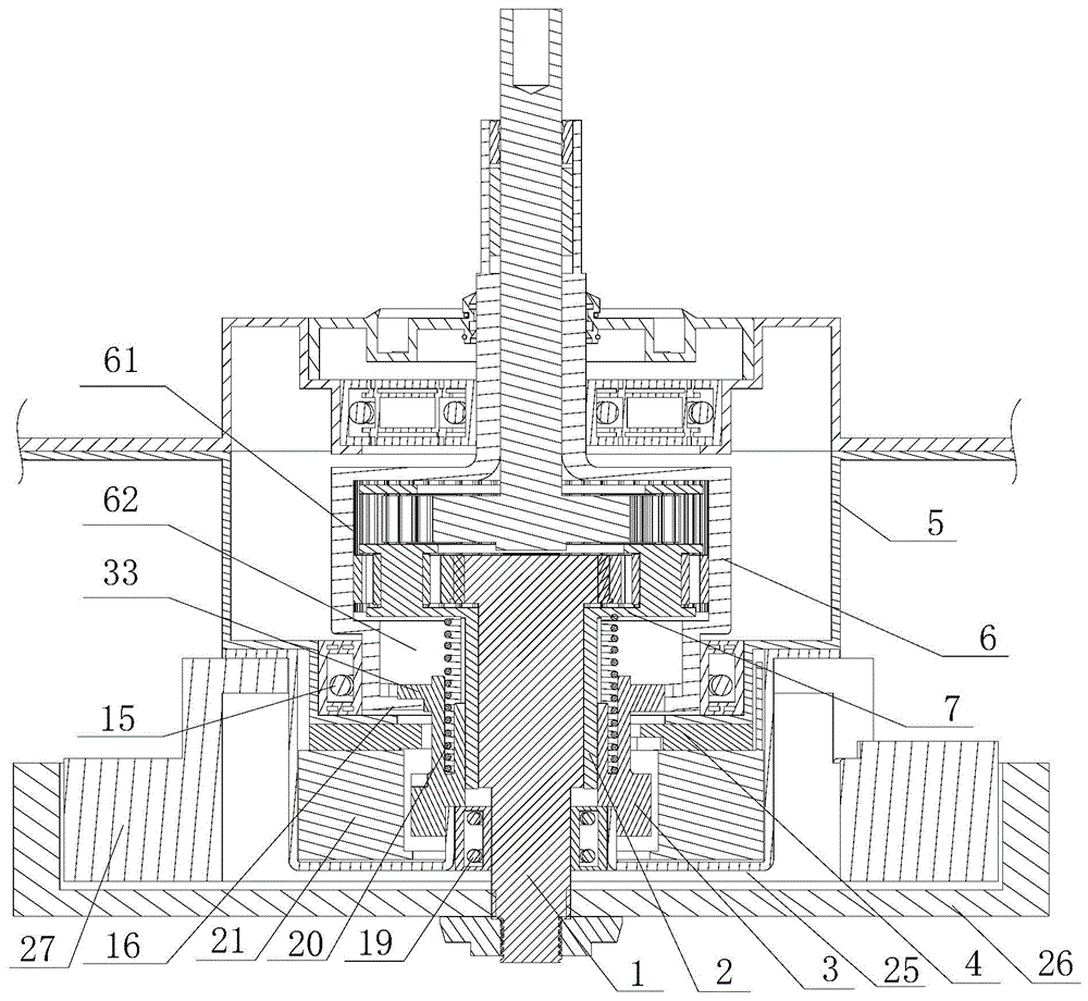
[0054] Such as figure 2 As shown, the internal gear 6 of the present invention is in an inverted convex shape as a whole, and the internal teeth meshing with the upper planetary gear 13 and the lower planetary gear 14 are arranged in the upper gear chamber 61, and the space of the upper gear chamber 61 is larger than that of the lower clutch chamber 62 spaces.

[0055] Further, a bearing 15 is provided between the internal gear 6 and the housing 5. Preferably, the bearing 15 is located at a position corresponding to the outside of the lower clutch chamber 62. More preferably, the housing 5 is in an inverted convex shape as a whole. The space surrounded by the lower peripheral wall, the bottom wall of the housing, the upper bottom wall of the inner gear and the lower peripheral wall constitutes the mounting portion 24 of the bearing 15 .


PUM


Abstract

The invention discloses a decelerating clutch of a full-automatic washing machine. The machine mainly comprises an input shaft, an input shaft sleeve, an output shaft, an output shaft sleeve, a clutching mechanism, a housing, and a planetary gear system mounted in the housing; the planetary gear system comprises a planetary mechanism, a planetary gear rack and an inner gear; the input shaft distributes and transmits power to the output shaft sleeve and the output shaft through the inner gear and the planetary mechanism; the clutching mechanism comprises a clutching sleeve which is connected with the input shaft by sliding up and down through a spline, a spin drying plate mounted on the inner gear, and a brake plate mounted on the housing; the clutching sleeve is connected and disconnected with the brake plate and the spin drying plate by sliding up and down so as to achieve clutching switching of washing and spin drying. The decelerating clutch has the characteristics of being simple and compact in structure, low in manufacturing cost, safe and reliable in transmission, and efficient.

Description

technical field [0001] The invention relates to a deceleration clutch mechanism of a washing machine, in particular to a deceleration clutch of a fully automatic washing machine which realizes two-way rotation and washing of a pulsator and an inner tub. Background technique [0002] At present, the function of the deceleration clutch of the pulsator type washing machine is generally to drive the pulsator to reciprocate after decelerating the bidirectional rotation of the motor. The conventional deceleration clutch is mainly composed of an input shaft, an output shaft, an output shaft sleeve, an input shaft sleeve, a brake wheel, a reduction mechanism installed inside the brake wheel, and a clutch component installed on the input shaft sleeve. In washing conditions, the output shaft is required to rotate repeatedly at low speed in both directions. The output shaft sleeve and the brake wheel are integrated. The deceleration mechanism generally only plays a simple deceleration ...

Claims


Application Information

Patent Timeline
Patent Type & Authority Applications(China)
IPC IPC(8): D06F37/40D06F17/08
CPCD06F17/08D06F37/40
Inventor 吕佩师张刚金田云刘跃滨
Owner QINGDAO HAIER WASHING MASCH CO LTD
Learn More