Rainproof laundry rack system and operating method thereof

A clothes drying rack and a technology for drying clothes, applied in the field of clothes drying racks, can solve the problems of reducing the utilization rate of balcony space, low drying efficiency, affecting living quality and the like

Active Publication Date: 2015-06-03
JIANGSU UNIV OF TECH
View PDF7 Cites 7 Cited by
  • Summary
  • Abstract
  • Description
  • Claims
  • Application Information

AI Technical Summary

Problems solved by technology

The existing drying racks generally adopt a built-in design, and the drying racks are installed on the balcony ceiling. Due to the limitations of the balcony, there is a disadvantage of low sunlight utilization rate, resulting in l

Method used


Image

  • Rainproof laundry rack system and operating method thereof
  • Rainproof laundry rack system and operating method thereof
  • Rainproof laundry rack system and operating method thereof

Examples


Embodiment 1)

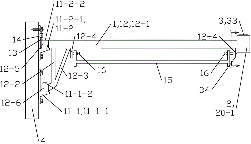
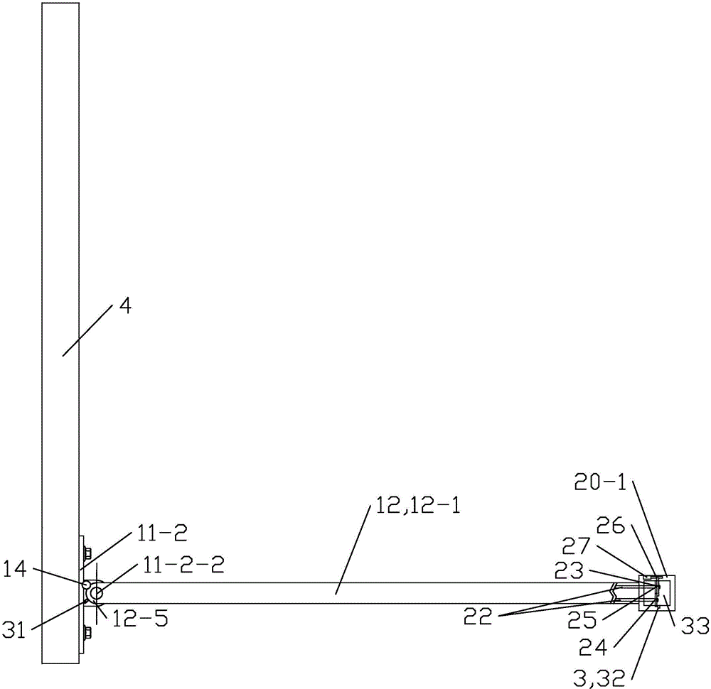
[0051] See figure 1 and figure 2 , The rainproof clothes drying rack system of this embodiment includes a clothes drying assembly 1 , a rainproof assembly 2 and a control system 3 .

[0052] still see figure 1 and figure 2 , The clothes drying assembly 1 includes a first bracket (11-1), a second bracket 11-2, a rotating arm 12, a first worm 13, a first motor 14, a clothes rail 15 and two clothes rail connecting rods 16. The first bracket (11-1) and the second bracket 11-2 are used to fix the whole rainproof clothes drying rack system on the wall 4 or the balcony railing, and the first bracket (11-1) includes a T that is turned left 90°. Shaped first main body 11-1-1 and the first cylindrical pin 11-1-2 vertically arranged on the first main body 11-1-1, the first main body 11-1-1 is formed from front to back, up and down The extended connecting plate is composed of a base plate connected to one side of the connecting plate along the left-right direction and the front-rear...

Embodiment 2)

[0057] The working method of rainproof clothes hanger system as described in embodiment 1, comprises following several steps:

[0058] ①When the rainproof clothes drying rack system is in the closed state, the rotating arm 12 of the clothes drying assembly 1 leans against the wall 4 or the balcony railing and is parallel to it. When the clothes to be dried are hung on the clothes drying rod 15, the user Press the drying switch of the control system 3, the drying switch is a system switch, the rainproof clothes hanger system works, the main control unit drives the first motor 14 to start, and the first motor 14 drives the rotating arm 12 to lean against the wall 4 or The position on the balcony railing begins to rotate and open. According to the feedback signal of the first angle sensor 31, it can be judged whether the actual opening angle reaches the set angle. After the rotating arm 12 rotates to the predetermined angle and reaches the drying position, the main control unit co...


PUM


Abstract

The invention relates to a rainproof laundry rack system and an operating method thereof. The rainproof laundry rack system comprises a drying component, a rainproof component and a control system. A rotating arm of the drying component can be driven by a first motor to open to a drying position or close to an initial position; the drying component comprises a drying bar used for drying clothing. The control system can control a second motor of the rainproof component to start up so as to control lowering or rolling of rain cloth. A master control unit controls the rain cloth through a signal sent by a rain sensor. The rain cloth is made of transparent waterproof material and is normally rolled on a rain cloth scroll and stored in the rotating arm. When the rain sensor senses rain, the second motor drives the rain cloth scroll to rotate, thereby lowering the rain cloth. In order to stably covering the clothing with the rainproof cloth, a sinker rod is tied to the bottom end of the rain cloth. If the rain is heavy, the first motor drives the rotating arm to rotate to one side of a balcony, thereby preventing the rain from being thrown to the clothing in the rain cloth by wind.

Description

technical field [0001] The invention relates to a daily necessities, in particular to a clothes drying rack. Background technique [0002] At present, with the deepening of urbanization in our country, apartment-style housing has become the mainstream of urban housing in our country, and the space of apartment-style housing is relatively compact, so how to dry clothes in a limited space has become a problem in apartment-style housing. The existing drying rack generally adopts a built-in design, and the drying rack is installed on the balcony ceiling. Due to the limitation of the balcony, there is a disadvantage of low sunlight utilization rate, resulting in low efficiency of drying clothes, and the balcony space occupied by the drying rack is large. It reduces the space utilization rate of the balcony and affects the space function use of the balcony, affecting the living quality. Contents of the invention [0003] The technical problem to be solved by the present inventi...

Claims


Application Information

Patent Timeline
IPC IPC(8): D06F57/12
CPCD06F57/12
Inventor 蒋科军张兰春刘成晔张焱王群山
Owner JIANGSU UNIV OF TECH
Why Eureka
Try Eureka