Water cooling heat dissipation module and charging pile module applying same

A heat dissipation module and charging pile technology, applied in charging stations, electric vehicle charging technology, cooling/ventilation/heating transformation, etc., can solve problems such as pollution, damage to charging pile templates, damage to devices, etc., to avoid dust pollution, avoid The effect of cooling effect

Inactive Publication Date: 2016-11-16
苏州科勒迪电子有限公司
View PDF7 Cites 10 Cited by
  • Summary
  • Abstract
  • Description
  • Claims
  • Application Information

AI Technical Summary

Problems solved by technology

At present, the charging pile templates in domestic charging stations are all high-power charging devices, and the multiple components contained in them will emit large heat (such as MOS tubes) during operation. Burned out, so the charging pile formwork is equipped with a cooling device for cooling the heat-generating components such as MOS tubes. The common cooling device is a fan fan. At the same time, dust and other substances will also be blown into the charging pile formwork, especially in dry climates (such as northern my country), it is easier to blow dust and other substances into the charging pile formwork. In the long run, the charging pile formwork will accumulate more Thick dust and other substances, when encountering a humid climate, dust and other substances will bond in the charging pile template, which will pollute and damage the charging pile template
[0004] In addition, not only the charging pile template, but also other devices with components that generate more heat during work, the cooling method is usually through fans, such as the main chassis of a desktop computer. In this way, the above-mentioned The conditions described above contaminate and damage the device

Method used


Image

  • Water cooling heat dissipation module and charging pile module applying same
  • Water cooling heat dissipation module and charging pile module applying same
  • Water cooling heat dissipation module and charging pile module applying same

Examples


Embodiment 1

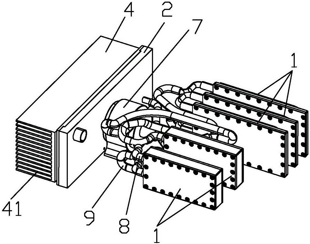
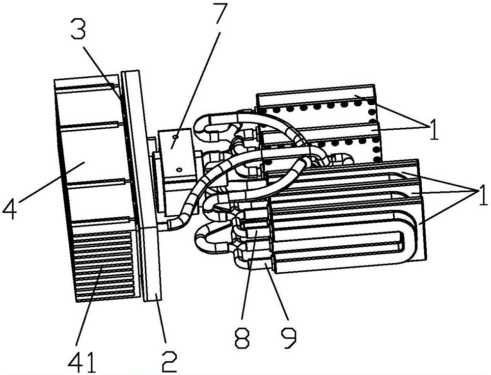
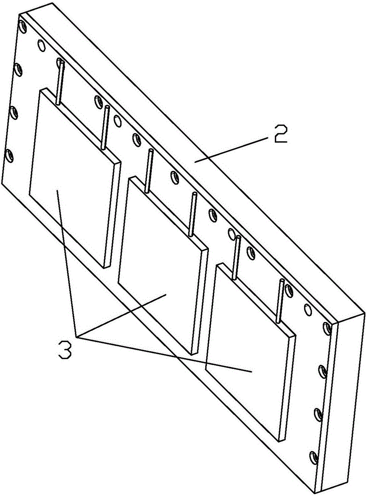
[0034] see Figure 1-7 A water-cooled heat dissipation module shown includes a heat absorbing block 1, a liquid storage block 2, a semiconductor refrigeration chip 3, and a radiator 4. The heat absorbing block 1 is provided with a liquid flow channel 11, and the liquid storage block 2 is provided with a The liquid storage tank, the liquid storage block 2 is connected with the heat-absorbing block 1, the inside of the two is a vacuum environment, and forms a circulation loop, the radiator 4 is located on the side of the liquid storage block 2 away from the heat-absorbing block 1, and between the two At least one semiconductor cooling chip 3 is attached, and the positive poles and negative poles of these semiconductor cooling chips 3 are respectively connected to the power supply.

[0035] As we all know, semiconductor cooling chip 3, also called thermoelectric cooling chip, is a kind of heat pump. Its advantage is that there are no sliding parts, and it is used in some occasio...

Embodiment 2

[0046] see Figure 1-8 As shown, a charging pile module adopting the above-mentioned water-cooled heat dissipation module includes a housing 5, and the housing 5 has an installation cavity 51, and one end of the installation cavity 51 is provided with a plurality of components K, and the installation cavity The other end in 51 is installed with the above-mentioned water-cooled heat dissipation module, the heat-absorbing block 1 is closely attached to or close to at least one component K, and the liquid storage block 2 forms an isolation zone between the radiator 4 and these components K, Therefore, these components K are accommodated in the relatively sealed area H formed by the casing 5 and the liquid storage block 2 .

[0047] The liquid storage block 2 forms an isolation zone between the radiator 4 and these components K, so that these components K are accommodated in the relative sealing area H formed by the housing 5 and the liquid storage block 2. This design can Avoid ...

Embodiment 3

[0050] see Figure 1-7 and Figure 9 The difference between this embodiment and the second embodiment of the charging pile module shown is that the above-mentioned water-cooled heat dissipation module is provided with at least one fan 6 inside the installation cavity 51, and the water-cooled heat dissipation module is located in these An isolation section is formed between the components and the fan 6 to prevent dust from blowing into the components. A cooling hole 53 is opened on the housing 5 at a position corresponding to the fan 6 . Setting the fan 6 can further improve the effect of heat dissipation. For the rest, the parts of the third embodiment that are the same as those of the second embodiment will not be repeated here.

[0051] Preferably, the fans 6 are arranged on the side of the radiator 4 away from the components, and there is a certain gap between them.

[0052] In addition, it should be noted that the water-cooled heat dissipation module provided by the pr...


PUM


Abstract

The invention discloses a water cooling heat dissipation module. The water cooling heat dissipation module comprises heat suction blocks, a liquid storage block, semiconductor refrigeration chips and a heat sink, wherein a liquid storage groove is formed in the liquid storage block and is used for storing a liquid, liquid flowing channels are arranged in the heat suction blocks, the liquid storage block communicates with the heat suction blocks, the interiors of the liquid storage block and the heat suction blocks are in vacuum environments to form a circulation loop, the heat sink is arranged on a side surface, far away from the heat suction blocks, of the liquid storage block, and at least one semiconductor refrigeration chip is pasted between the liquid storage block and the heat suction blocks. The invention also discloses a charging pile module applying the above water cooling heat dissipation module. The water cooling heat dissipation module is arranged in the shell, the heat suction blocks are in close contact or are near to at least one component, and isolation strips are formed between the liquid storage block and the heat sink, and between the liquid storage block and the components. By the water cooling heat dissipation module, the purposes of heat dissipation and dust pollution prevention are simultaneously achieved, and thus, the defect of the prior art is overcome.

Description

technical field [0001] The invention relates to the field of heat dissipation devices, in particular to a water-cooled heat dissipation module and a charging pile module using the water-cooled heat dissipation module. Background technique [0002] With the rapid development of new energy vehicles, the global sales of electric vehicles continue to grow. At present, most of the energy storage systems of electric vehicles use lithium-ion batteries. Lithium-ion batteries have the advantages of high energy ratio and light weight. The battery uses an organic electrolyte, which is flammable and explosive. It is inherently poor in safety and has the risk of explosion, which brings great hidden dangers to electric vehicles. The electrolyte of domestic nickel-metal hydride power batteries (supercapacitors) is aqueous electrolyte, which fundamentally solves the problem of flammability and explosion of batteries. After years of development, the large capacity of nickel-hydrogen power ba...

Claims


Application Information

Patent Timeline
Patent Type & Authority Applications(China)
IPC IPC(8): H05K7/20H05K5/02B60L11/18
CPCB60L53/31H05K5/0213H05K7/20136H05K7/20218Y02T10/70Y02T10/7072Y02T90/12
Inventor 杨强
Owner 苏州科勒迪电子有限公司
Why Eureka
Try Eureka