Automatic transmission

a transmission and automatic technology, applied in the direction of fluid gearing, machines/engines, fluid gearings, etc., can solve the problems of breather oil blowing, oil leakage from the sealed portion of the oil seal into the converter housing, etc., and achieve the effect of preventing breather oil blowing

Inactive Publication Date: 2005-09-27
AISIN AW CO LTD
View PDF8 Cites 11 Cited by
  • Summary
  • Abstract
  • Description
  • Claims
  • Application Information

AI Technical Summary

Benefits of technology

[0009]Accordingly, it is an object of the present invention to provide an automatic transmission constructed to prevent breather oil blow by preventing oil discharged from an oil drain passage into a mission case from being spattered toward part of the transmission mechanism

Problems solved by technology

With such a structure, however, during the operation of the oil pump, the operating oil that is sequentially fed fills the fluid reservoir to increase the pressure, thereby sometimes causing oil leakage from the sealed portion with the oil seal into a converter housing.
With the above oil pump structure, however, the operating oil discharged through the oil drain passage into the mission case is spattered around a rotating drum that supports a brake and so on housed in the case, thus having the problem of causing breather oil blow such that the operating oil is stirred by the high speed drum to foam while generating oil drag.

Method used


Image

  • Automatic transmission
  • Automatic transmission
  • Automatic transmission

Examples


Embodiment Construction

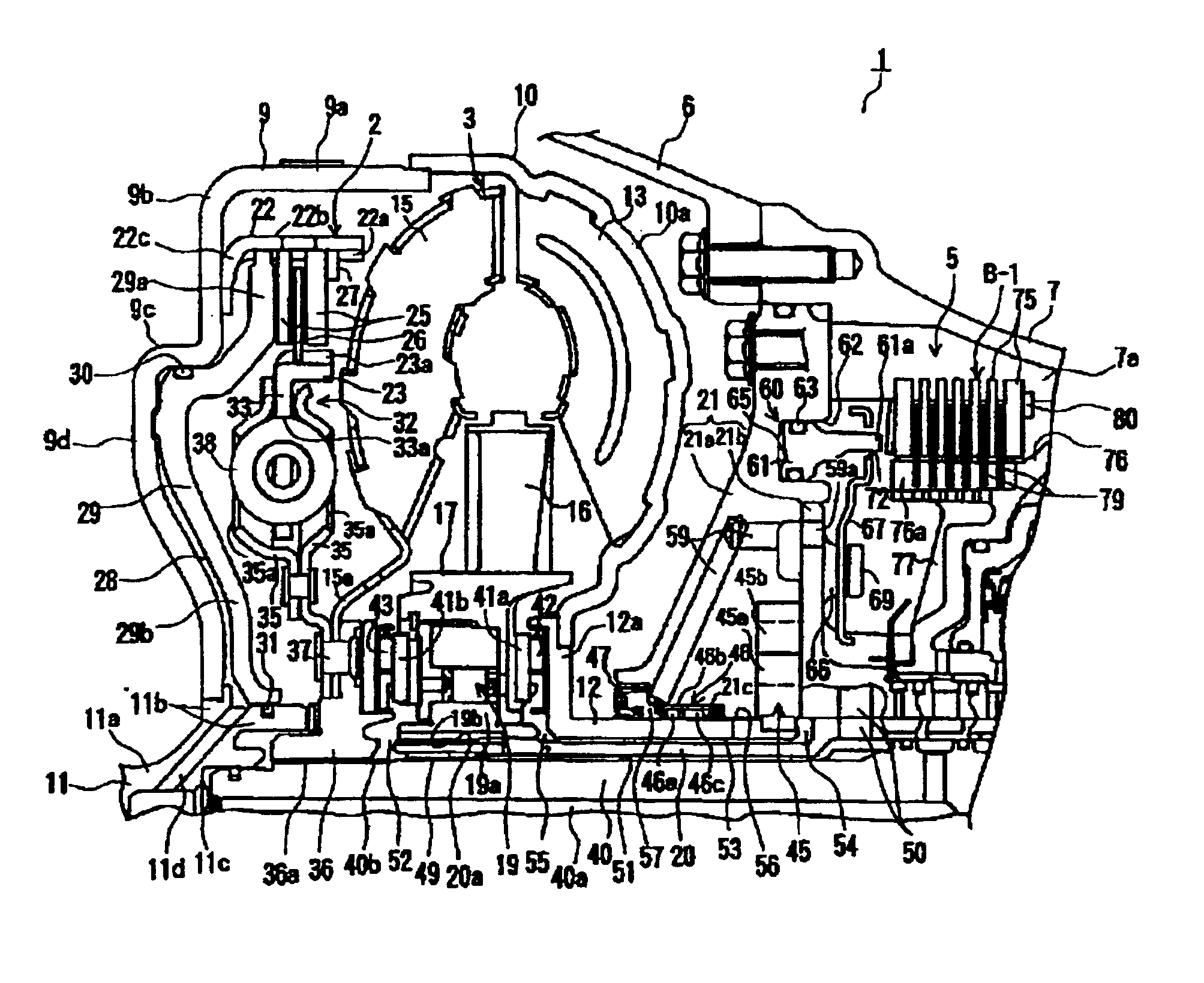
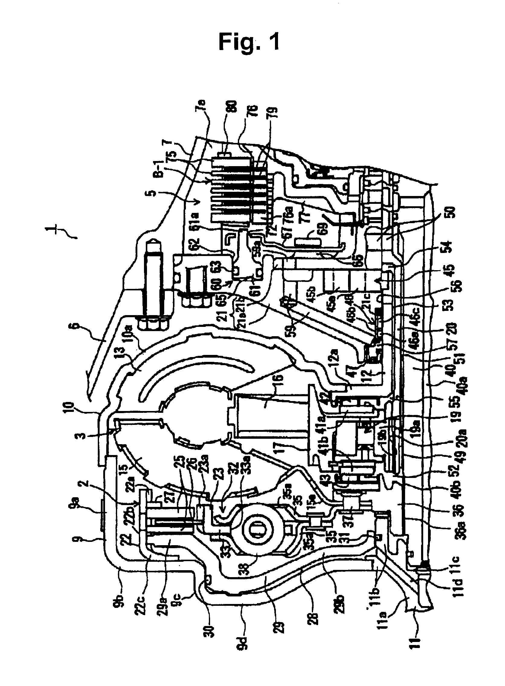
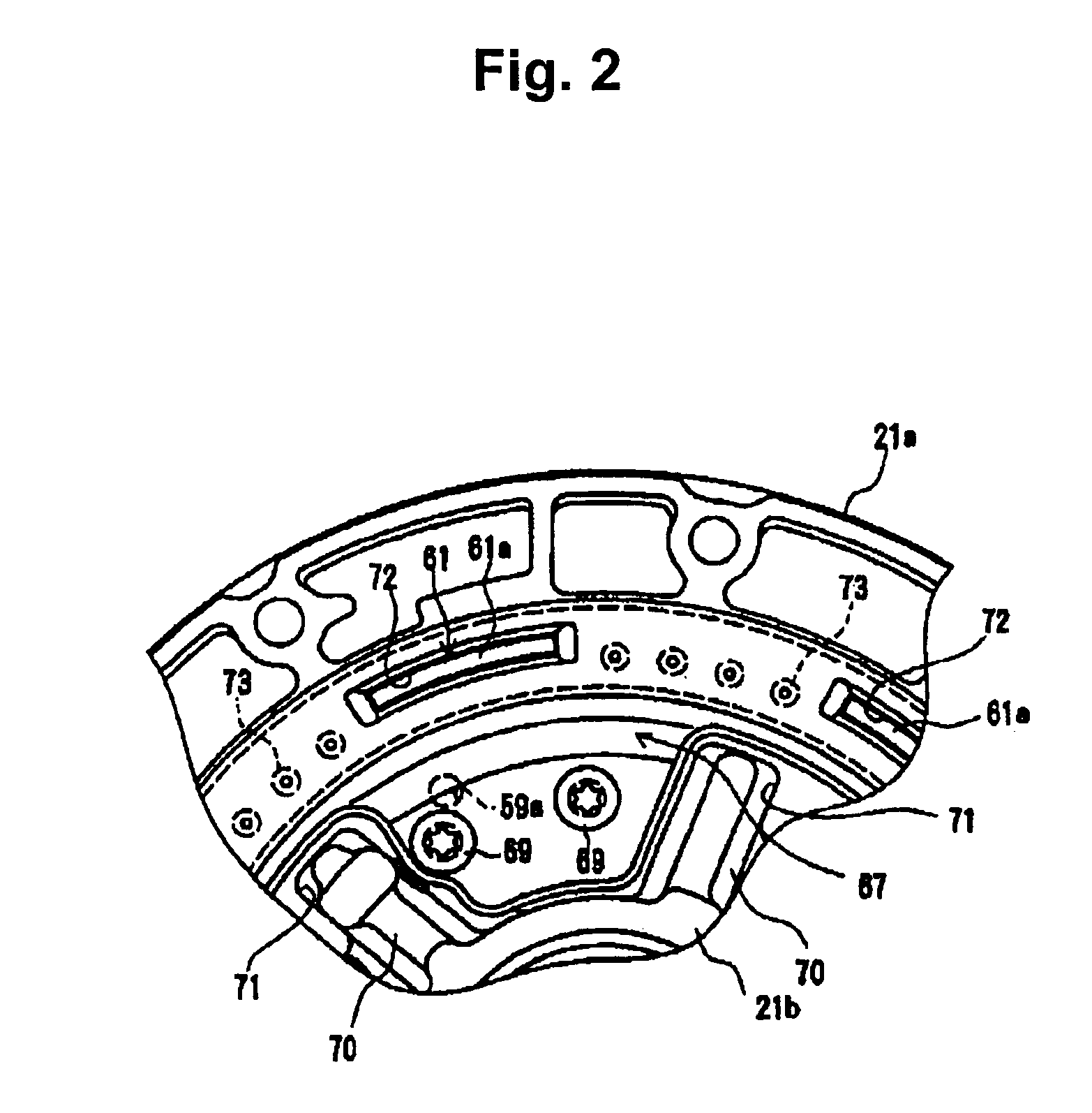
[0014]While the invention is open to various modifications and alternative forms, specific embodiments thereof are shown by way of examples in the drawings and are described herein in detail. There is no intent to limit the invention to the particular forms disclosed. FIG. 1 is a sectional view, on a partially enlarged scale, of an automatic transmission 1 according to an embodiment of the present invention; FIG. 2 is a side view of a hydraulic actuator 60 disposed in a pump casing 21, seen from a brake B-1 in FIG. 1; and FIG. 3 is an enlarged sectional view of a roller bearing 46 disposed between a pump drive shaft 12 and a bearing hole 21c. Referring to FIG. 1, the left of the automatic transmission 1 is connected to an internal-combustion engine (not shown) such as a gasoline engine.

[0015]Referring to FIG. 1, the automatic transmission 1 includes a lockup clutch 2, a torque converter 3, and a multistage transmission mechanism 5 to which a driving force (output rotation) from the ...


PUM


Abstract

A transmission has an oil drain passage for connecting an oil reservoir with a mission case in a pump casing. The automatic transmission has also a retainer serving as a shielding member to shield between a discharge opening of the oil drain passage from at least part of a multistage transmission mechanism. This ensures that breather oil blow, which is caused by the spattering and stirring of operating oil by the high-speed drum member, is shielded from at least part of the transmission mechanism.

Description

[0001]This application claims priority from Japanese Patent Application JP 2002-231303, which was filed on Aug. 8, 2002 and is incorporated herein by reference.BACKGROUND OF THE INVENTION[0002]1. Field of the Invention[0003]The present invention relates to an automatic transmission, and more particularly, concerns an automatic transmission with improvements in draining oil for lubricating between a pump drive shaft for driving a pump unit and a bearing hole for supporting the drive shaft.[0004]2. Description of the Related Art[0005]For example, with an oil pump driven by the output rotation of an engine to supply an automatic transmission fluid (hereinafter, referred to as an ATF) to each component of an automatic transmission, the output rotation is transmitted through a sleeve-like pump drive shaft connected to a pump impeller of a torque inverter. The ATF (also referred to as oil or operating oil in the present specification) pumped from the oil pump is supplied for lubrication t...

Claims


Application Information

Patent Timeline
Patent Type & Authority Patents(United States)
IPC IPC(8): F16H57/04F16H45/00F16H45/02F16H57/027
CPCF16H57/0436F16H45/02F16H57/045Y10T74/2186F16H2045/0284Y10T74/19991F16H57/0471
Inventor IDA, MASAHIROIKE, NOBUKAZUKASUYA, SATORUNISHIDA, MASAAKIHAYABUCHI, MASAHIROOKUNO, MITSUTAKA
Owner AISIN AW CO LTD
Why Eureka
Try Eureka