Heat pipe type heat radiation module and charging pile module employing same
A heat dissipation module and charging pile technology, applied in charging stations, electric vehicle charging technology, electric vehicles, etc., can solve problems such as pollution, damage to charging pile templates, and damage to devices
- Summary
- Abstract
- Description
- Claims
- Application Information
AI Technical Summary
Problems solved by technology
Method used
Image
Examples
Embodiment 1
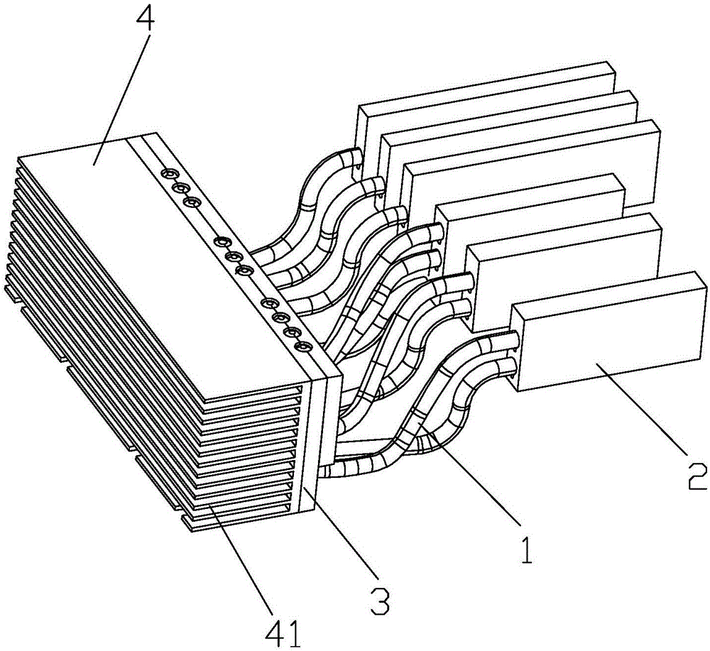
[0028] see figure 1 A heat pipe type cooling module shown in , includes a heat pipe 1, the heat pipe 1 includes a heat absorbing end and a condensing end, the heat absorbing end is provided with a heat absorbing plate 2, and the condensing end is provided with a heat conducting plate 3, and the heat conducting plate 3 is far away from the condensing end A radiator 4 is attached to the side.
[0029] Preferably, the heat absorbing plate 2 is provided with first insertion holes corresponding to the number of heat pipes 1 , and the heat absorption ends are inserted into the first insertion holes. Certainly, the heat-absorbing end of the heat pipe 1 and the heat-absorbing plate 2 can also be connected by means of riveting / welding, etc., and are not limited to the connection method of inserting.
[0030] Preferably, the heat conduction plate 3 is provided with second insertion holes corresponding to the number of heat pipes 1 , and the condensing end is inserted into the second in...
Embodiment 2
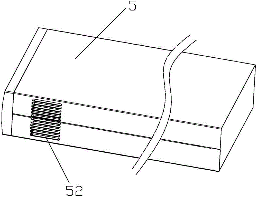
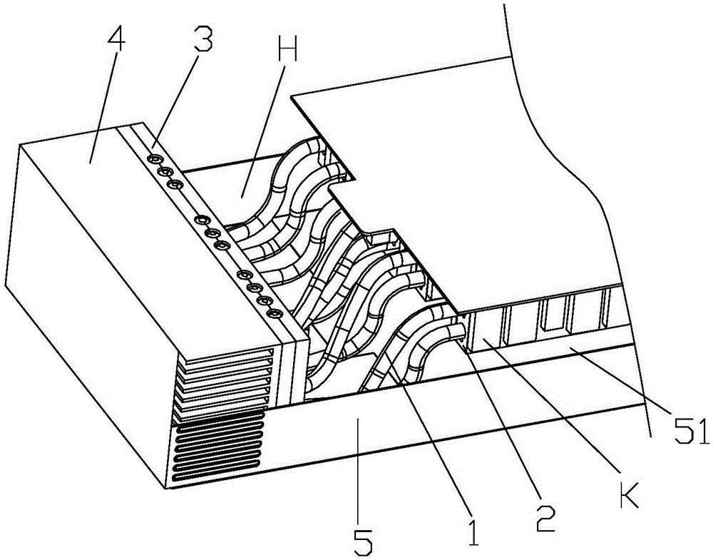
[0036] see Figure 2-3 As shown, a charging pile module adopting the above-mentioned heat pipe type heat dissipation module includes a housing 5, and the housing 5 has an installation cavity 51, and one end of the installation cavity 51 is provided with a plurality of components K, and the installation cavity The other end of the 51 is installed with the above-mentioned heat pipe type heat dissipation module, the heat absorbing plate 2 is closely attached to or close to at least one component K, and the heat conducting plate 3 forms a natural isolation zone between the radiator 4 and these components K , so that these components K are accommodated in the relatively sealed area H formed by the housing 5 and the heat conducting plate 3 .
[0037] The heat conduction plate 3 forms an isolation zone between the radiator 4 and the component K, so that the component K is accommodated in the relatively sealed area formed by the shell 5 and the heat conduction plate 3. This design can...
Embodiment 3
[0041] see Figure 4 The difference between this embodiment and Embodiment 2 of the charging pile module using the heat pipe type heat dissipation module shown above is that at least one fan 6 is also arranged in the installation cavity 51, and the heat pipe type heat dissipation module is located in these An isolation section is formed between the component K and the fan 6 to prevent dust from blowing into the component K. A cooling hole 53 is opened on the housing 5 at a position corresponding to the fan 6 . Setting the fan 6 can further improve the effect of heat dissipation. For the rest, the parts of the third embodiment that are the same as those of the second embodiment will not be repeated here.
[0042] Further, the fans 6 are arranged on the side of the radiator 4 away from the components K, and there is a certain gap between them.
[0043] In addition, it should be noted that the heat pipe type heat dissipation module provided by the present invention is not limi...
PUM
 Abstract
Description
Claims
Application Information
 - R&D
- Intellectual Property
- Life Sciences
- Materials
- Tech Scout
- Unparalleled Data Quality
- Higher Quality Content
- 60% Fewer Hallucinations
Browse by: Latest US Patents, China's latest patents, Technical Efficacy Thesaurus, Application Domain, Technology Topic, Popular Technical Reports.
© 2025 PatSnap. All rights reserved.Legal|Privacy policy|Modern Slavery Act Transparency Statement|Sitemap|About US| Contact US: help@patsnap.com


