Roof ridge ventilation system

a ventilation system and roof ridge technology, applied in ventilation systems, lighting and heating apparatus, heating types, etc., can solve the problems of not revealing the use of ridge vent systems, insufficient for today's larger structures with greater ventilation and cooling needs, and inability to operate easily, reduce the effect of heat transfer, and facilitate operation

Active Publication Date: 2015-10-13
DIGITAL CONTROL SYST
View PDF41 Cites 11 Cited by
  • Summary
  • Abstract
  • Description
  • Claims
  • Application Information

AI Technical Summary

Benefits of technology

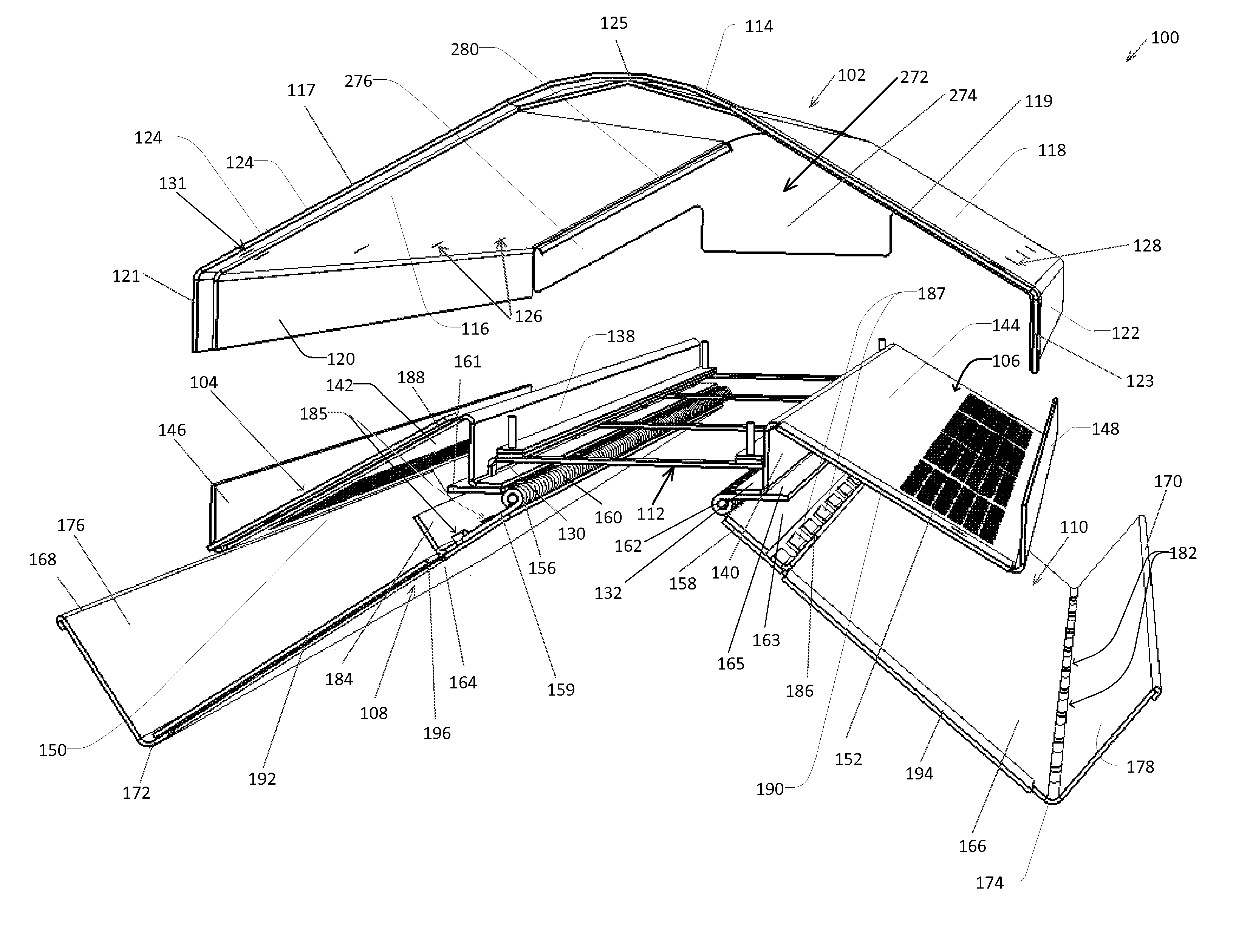
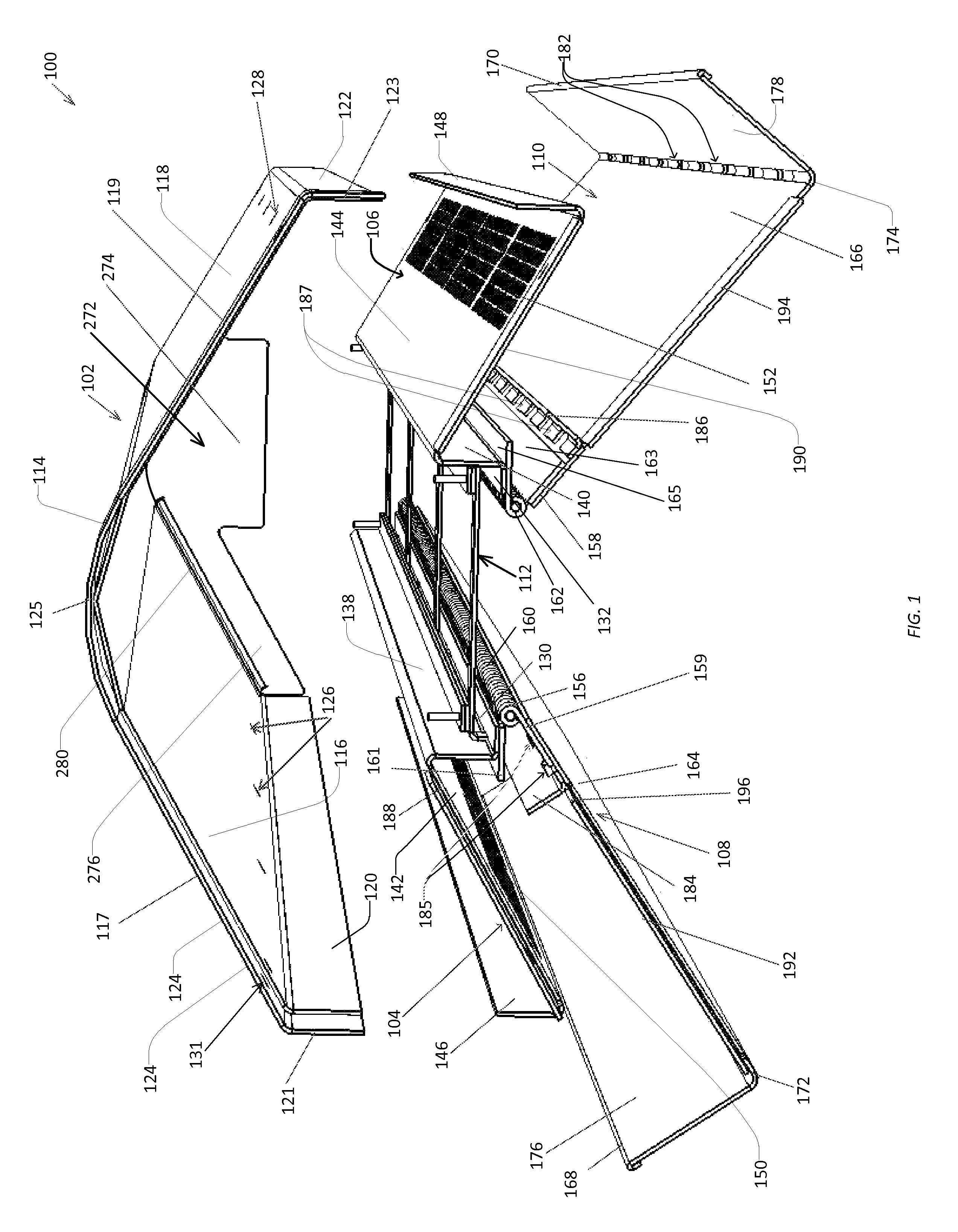
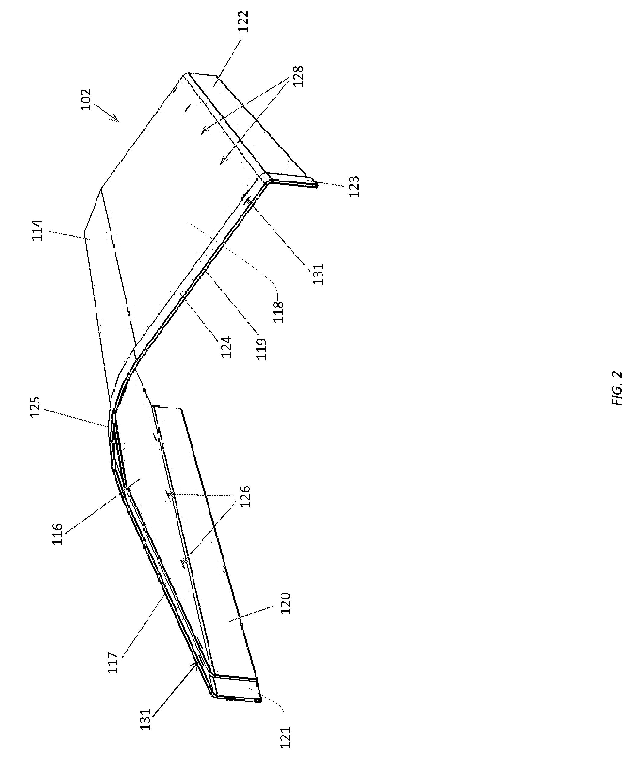
[0034]Further, the roof ridge ventilation system preferably comprises a second wall on each of the base members and that is attached to, or extends from, the base member and preferably extends along the length of the base member, the second wall being adapted for preventing water from being blown into the hinge or hinges between the vent member and the base member. This second wall is thus adapted for preventing water from being blown upwardly along the base by the wind and into the opening at the ridge of the roof, in order to prevent water from getting into any of the vent chutes, roofing materials, insulation, attic or house. The second wall also preferably comprises an L-shaped attachment portion for attachment of each wall to the base member at a location beneath the vent member and the hood, the second wall for preventing blowing of water into the opening in the ridge also comprising drainage means, such as spaced holes defined near a base portion and the attachment portion of the second wall, for allowing drainage of condensate or other water to drain through and away from the second wall, down the base member and to the gutter or wall portion of the base member for blocking wind to allow drainage therefrom through drainage holes in the gutter or wall portion for blocking wind.
[0058]Proper ventilation of a roof's vent chutes with the present invention minimizes the transfer of heat from the roof to the rest of the structure, especially during warmer periods. While the present invention includes both active and passive ventilation aspects and embodiments, active ventilation of the vent chutes with a fan-assisted ventilation system is the most effective means of cooling a vaulted ceiling structure and of preventing moisture buildup in the roofing materials, in that such ventilation creates a uniform and consistent airflow along the location where ventilation is needed most, along the underside of the solid sheath. Proper ventilation of the vent chutes of a roof creates a thermal insulation barrier preventing radiation of heat into the structure and helps prevent “hot spots” that otherwise would develop under the roof's solid sheath and that would reduce the effectiveness of the ventilation means leading to reduced roof life. While the primary application of the present invention is to actively ventilate the vent chutes of a vaulted ceiling roof, of course, the present invention is also readily adaptable to actively, or passively, ventilate attic or other spaces of a structure.

Problems solved by technology

Though such ridge vent systems have been naturally more efficient than spot ventilation systems, since warm air naturally rises upwardly toward the ridge of the roof and since they have been able to ventilate the attic space or vent chutes all along the ridge of the roof closely adjacent the area where the warm air first rises to the peak of the roof, their effectiveness has been limited where stagnant wind conditions, higher temperatures and higher moisture and humidity have been present.
Villela does not disclose the use of a ridge vent system adapted for housing a fan array within the ridge vent for actively ventilating the vent chutes of a roof.
Morris does not teach the use of a ridge vent system adapted for having a fan array in the ridge vent for actively ventilating vent chute airspace communicating between a ridge vent, soffit vents, insulation and solid sheathing materials.
These prior art systems have not accounted for the fact that certain roof lines facing a certain direction may not be oriented to take advantage of prevailing winds to create adequate passive airflow, have not accounted for the fact that sometimes weather and excess humidity conditions have not been conducive to adequate passive ventilation airflow, and have not generally been adequate for today's larger structures having greater ventilation and cooling needs.
Thus, while passive ridge vents have been developed which take advantage of natural wind and convective air currents to create natural areas of lower pressure outside of the ridgeline of the roof to induce warm air to travel upwardly and outwardly to the exterior at the ridge vents, varying weather, rain, humidity and wind conditions, together with enhanced needs for ventilation in today's modern structures, have created conditions which passive ventilation systems simply cannot adequately ventilate—no matter how well they have been designed.

Method used


Image

  • Roof ridge ventilation system
  • Roof ridge ventilation system
  • Roof ridge ventilation system

Examples


Embodiment Construction

[0077]Referring to FIGS. 7a-c, roofs 10 are shown, roof 10 of FIG. 7a covering an attic space 22, roof 10 of FIG. 7b covering a vaulted or cathedral ceiling (hereafter referred to as vaulted ceiling) and roof 10 of FIG. 7c covering an attic space 22 but in the less common situation where there is encountered both attic floor insulation 25 as well as roof insulation 24 so that there are vent chutes 226 as shown.

[0078]Each roof 10 is composed of structural members, such as rafters 12 joined together so as to form a peak or ridge portion 217 shown in the figures having a beam 215. On either side of the ridge 217 there are typically fastened sheets of plywood 16 serving as a base or solid sheath 16 for installing, as by nailing, roofing material, such as shingles, shakes and the like (all represented by 18).

[0079]As shown in FIGS. 7b and 7c, on the underside of the typically plywood solid sheath 16, there is defined between the rafters 12 an air gap 20, or in actuality a plurality of ai...


PUM

PropertyMeasurementUnit
lengthaaaaaaaaaa
lengthaaaaaaaaaa
angleaaaaaaaaaa

Abstract

Roof ridge vent system adapted for housing a plurality of fans in a central airflow channel positioned directly over the opening in a ridge portion of a roof for ventilating a plurality of vent chutes or attic space comprising: a hood member engaged with outer edge portions of vent members having air-passageway holes defined therein and inner edge portions preferably being hinged respectively to inner edge portions of base members so as to be adapted for installation on variously-pitched roofs, each base member also having outer edge portions defining a wall adapted for blocking wind from being blown into the vent and for causing airflow over the top of the vent to encourage airflow through the vent system. Vent member sections may be installed end-to-end to define an elongated airflow channel adapted for ventilating with or without assistance from the fans.

Description

FIELD OF INVENTION[0001]This invention relates generally to roof ventilation systems and more specifically to an energy-saving roof ridge ventilation system that is easily adapted for use on a number of variously-pitched roofs, that is adapted for use with a plurality of fans either for ventilating internal vent chutes defined by roofing and insulation materials or for ventilating attic space.BACKGROUND OF INVENTIONThe Need For Ventilation of Vent Chutes and Attic Spaces[0002]As an energy saving means, many homes and roofs are well-insulated and built to tighter tolerances to prevent escape of heating, or alternatively cooling, air. A typical pitched roof comprises a base portion of the roof, known as a solid sheath, which is nailed or otherwise joined to an upper portion of structural rafters for providing a solid surface upon which shingles or other roofing materials are installed.[0003]In particular for today's more modern vaulted ceiling and cathedral ceiling roofs (referred to ...

Claims


Application Information

Patent Timeline
Patent Type & Authority Patents(United States)
IPC IPC(8): B61D17/14E04D13/17E04B7/00F24F7/02
CPCE04D13/17E04D13/174Y10T29/49826Y02B10/20F24F7/025
Inventor ALLEN, DONKAMANI, JAYLE, PHUONG
Owner DIGITAL CONTROL SYST
Why Eureka
Try Eureka