Foundation pit anti-floating anchor rod pull-out test tool

A technology of anti-floating anchor rod and pull-out test, applied in the test of basic structure, basic structure engineering, construction, etc., can solve the problems of wasting time, labor and materials, affecting efficiency, etc., to reduce costs and achieve simple and easy operation. performance, improve work efficiency

Active Publication Date: 2015-06-03
GUANGZHOU MUNICIPAL ENG DESIGN & RES INST CO LTD
View PDF5 Cites 11 Cited by
  • Summary
  • Abstract
  • Description
  • Claims
  • Application Information

AI Technical Summary

Problems solved by technology

The test of the bearing capacity of the anti-floating anchor rods uses the through-hole jack to carry out the on-site pull-out test. In the traditional pull-out test, the through-hole jack is passed through the entire group of anchor bars, and then a section of steel bar is welded on the upper part of the anchor bars. Therefore, the upward force of the jack is transmitted to the anchor bar. There are several problems in this method: 1. In the case of 3-4 anchor bars, a large-caliber jack must be used, otherwise the core will not be able to pass through; 2. In order to ensure that the test can be carried out, the length of the anchor bar exposed to the ground must be more than 1.5m, otherwise it must be extended with welded steel bars, which is wasteful; 3. When the anchor bar exposed to the ground is very long or slightly bent, it is very laborious to pass through the center, which affects the efficiency ;4. Every time a group of tests is done, the steel bars have to be welded and cooled, which wastes time and affects efficiency
[0004] Chinese patent CN203908864U discloses a simple supporting tool for pulling out a tunnel anchor rod, wherein the anchor rod does not need to be reserved for a long time, even if it is too short, it does not need to be welded and lengthened, and the supporting tool includes a connecting sleeve with an internal thread and a lengthened anchor The extended end of the anchor rod is provided with a connecting thread and is threaded with the connecting sleeve. One end of the extended anchor rod is also provided with a connecting thread and is threaded with the connecting sleeve. Through the connecting sleeve and the extended anchor rod, the anchor rod Extend and then load, however, this method is only applicable to the case of a single anchor bar, and the protruding end of the anchor bar needs to be provided with a thread consistent with the specification of the connecting sleeve in advance, which has poor applicability
[0005] Chinese patent CN203229975U discloses a steel tendon anchoring fixture device, which improves the time-consuming and wasteful problems of steel bar welding and welding in traditional tests, but still has several other disadvantages: 1. When there are many steel bars in a steel tendon, a small-diameter jack cannot pass through ; 2. The anchor bar must be exposed to the ground for a long time, otherwise it must be welded to lengthen, which is labor-intensive; 3. When the anchor bar exposed to the ground is very long or slightly bent, it will take a lot of effort to pass through the center, which will affect the efficiency

Method used


Image

  • Foundation pit anti-floating anchor rod pull-out test tool
  • Foundation pit anti-floating anchor rod pull-out test tool
  • Foundation pit anti-floating anchor rod pull-out test tool

Examples


Embodiment Construction

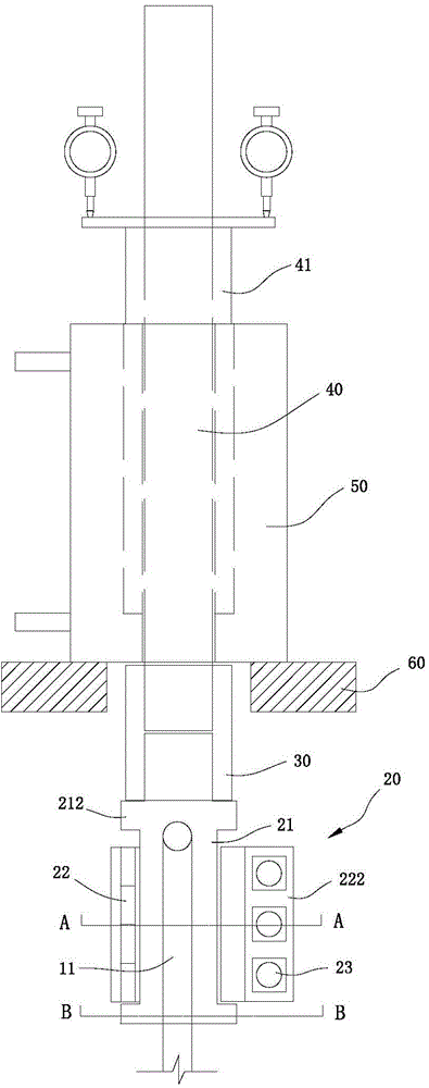
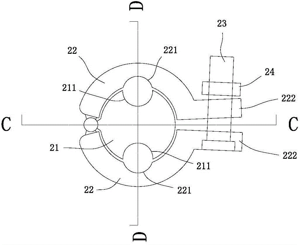
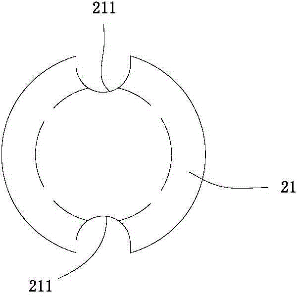
[0023] refer to Figure 1 to Figure 5 , a foundation pit anti-floating anchor pull-out test tool, including an anchor bar composed of several anchor tendons 11, an anchor bar locking assembly 20 composed of a locking bar 21 and a locking member, a connecting sleeve 30, and an extended anchor bar 40 And the through-core jack 50, the upper end of each anchor bar 11 in the anchor bar is bent symmetrically from the center outward to form a bending part 12, and the outer wall of the lower part of the lock bar 21 is vertically provided with a plurality of slots for the anchor bars 11 to be embedded and placed at symmetrical intervals 211, the locking member is fastened on the lower part of the locking bar 21 to lock the anchor bar 11 in the channel 211, the middle part of the locking bar 21 has a step structure 22 that resists the bending part 12 of the anchor bar 11, and the upper end of the locking bar 21 is connected to the The lower ends of the extended anchor rods 40 are connec...


PUM


Abstract

The invention discloses a foundation pit anti-floating anchor rod pull-out test tool. The tool comprises an anchor rod, an anchor rod locking component, a connecting sleeve, a lengthened anchor rod and a center-penetrating jack, wherein the anchor rod consists of a plurality of anchor ribs; the anchor rod consists of a locking rod and a locking buckle component; the upper end of each anchor rib in the anchor rod is symmetrically bent from the center to the outside to form a bent part; a plurality of groove ways for placing the anchor ribs are symmetrically and vertically arranged on the outer wall of the lower part of the locking rod at intervals; the locking buckle component is arranged on the lower part of the locking rod in a buckling way to lock and fix the anchor ribs in the groove ways; a step structure pushing against the bent parts of the anchor ribs is arranged on the middle part of the locking rod; the upper end of the lock rod and the lower end of the lengthened anchor rod are linked together through the connecting sleeve; the lengthened anchor rod is linked with the center-penetrating jack; the lock rod and the lengthened anchor rod can be quickly connected together through the anchor rod locking component. The center-penetrating jack applies a pull-out force to the lengthened anchor rod and transfers the force to the anchor rod, so that a pull-out test is performed; according to the pull-out test tool, the traditional structure form is eliminated, lengthened anchor ribs are not used, welding is not required, and the tool can be repeatedly used, so that the cost is effectively reduced, and the working efficiency is improved.

Description

technical field [0001] The invention relates to the technical field of an anti-floating anchor pullout test device in construction engineering, in particular to a foundation pit anti-float anchor pullout test tool. Background technique [0002] Anti-floating anchor rods, also called anti-floating piles, are a kind of anti-floating measures for underground structures in construction projects. Anti-floating anchors are different from ordinary foundation piles, and have their own unique properties. The biggest difference from ordinary foundation piles is that foundation piles are usually compression piles, and the pile body bears the building load pressure, and the force is from the top of the pile to the bottom of the pile. Transmission, the force on the pile body changes with the change of the building load; while the anti-floating pile is anti-pull, the pile body bears the tensile force, and the force on the ordinary anti-floating pile is also transmitted from the top of th...

Claims


Application Information

Patent Timeline
Patent Type & Authority Applications(China)
IPC IPC(8): E02D33/00
Inventor 李广平彭功勋陈荣彬徐鲁华鲁传恒
Owner GUANGZHOU MUNICIPAL ENG DESIGN & RES INST CO LTD
Why Eureka
Try Eureka