
Embedded bolt positioning method and positioning frame applied to same

A technology of pre-embedding bolts and frames, applied in the processing of building materials, infrastructure engineering, construction, etc., can solve the problems of inaccurate bolt positioning, troublesome production, large welding workload, etc., to reduce the construction welding workload, use Flexible and convenient, flexible and accurate positioning effect

Inactive Publication Date: 2015-06-03
GUIYANG AL-MG DESIGN & RES INST
View PDF5 Cites 2 Cited by
  • Summary
  • Abstract
  • Description
  • Claims
  • Application Information

AI Technical Summary

Problems solved by technology

In the former construction method, when the bolts are pre-embedded, the position of the bolts is not easy to grasp, and the problem of inaccurate bolt positioning often occurs, which brings inconvenience to the installation, and sometimes even needs to be removed and re-embedded
Although the second method can solve the problem of inaccurate positioning of the former method, it is generally made on site by the construction unit. A set of positioning frames can only meet the use of the same foundation, the same bolts, and the same positioning, that is, it has a one-time Features, can not be adjusted flexibly to meet the use requirements of different foundation embedded bolts
When making the positioning frame, the welding workload is heavy, a set of positioning frame can only adapt to one basic structure, the versatility is poor, and the production is troublesome

Method used


Image

  • Embedded bolt positioning method and positioning frame applied to same
  • Embedded bolt positioning method and positioning frame applied to same
  • Embedded bolt positioning method and positioning frame applied to same

Examples


Embodiment Construction

[0020] The present invention will be further described in detail below in conjunction with the accompanying drawings and embodiments, but not as any limitation to the present invention.

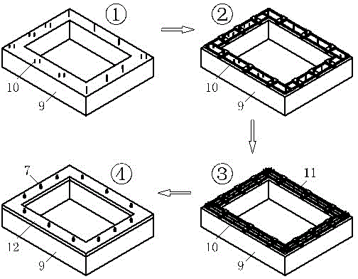
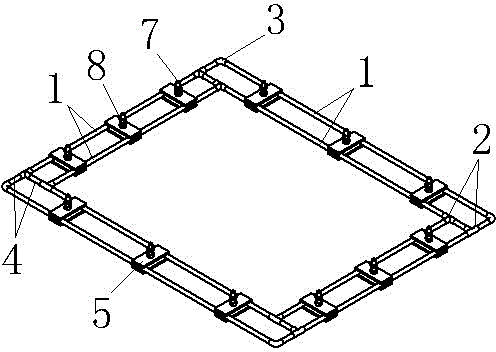
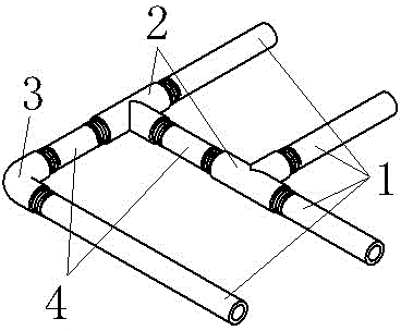
[0021] Example. A method for positioning pre-embedded bolts, the method is to use steel pipes, elbows 3 and tees 2 to form a back-shaped frame, fix a group of pre-embedded bolt assemblies on the parallel steel pipes on the four sides of the back-shaped frame according to design requirements, and then Place the zigzag frame on the top surface of the foundation, with the thread heads of the embedded bolts 7 facing upwards, and pour the zigzag frame fixed with the embedded bolts on the foundation with concrete. The pre-embedded bolt assembly includes two splints 5 arranged at the bottom and top of the zigzag frame. The embedded bolts 7 are passed through the bolt holes 6 of the two splints 5 from bottom to top, and the two splints 5 are adjusted in the zigzag frame. After the upper position...


PUM


Abstract

The invention discloses an embedded bolt positioning method and a positioning frame applied to same. The embedded bolt positioning method comprises connecting steel tubes, elbows and tee joints into a hollow-square-shaped frame; fixing a group of embedded bolt modules into parallel steel tubes on four edges of the hollow-square-shaped frame according to design requirements; then placing the hollow-square-shaped frame onto the top surface of a foundation in a mode that the head portions of embedded bolts are placed upwards; pouring the hollow-square-shaped frame with the embedded bolts onto the foundation. According to the embedded bolt positioning method, the pipes are connected into the hollow-square-shaped frame; by selecting long pipes of different lengths, the dimensions of the inner frame and the outer frame of the hollow-square-shaped frame can be adjusted freely, and by selecting short pipes of different lengths, the spacing between the inner frame and the outer frame of the hollow-square-shaped frame can be adjusted to adapt to embedded bolts with different foundations, different diameters and different positioning requirements; during site construction, the embedded bolts can be positioned and fixed flexibly and accurately, use flexibility and convenience can be obtained, and construction welding workload can be reduced.

Description

technical field [0001] The invention relates to a positioning method for embedded bolts and a used positioning frame, belonging to the technical field of embedded bolts in building construction. Background technique [0002] In building construction, according to the needs of construction or equipment installation, some bolts are often pre-embedded for connection with other components or equipment. At present, the construction of pre-embedded bolts is to weld an anchor bar perpendicular to the bolt at the head of the bolt, and then pour the end welded with the anchor bar into the concrete according to the design position. Components or equipment connections. Or first weld a positioning frame, then the head of the bolt is welded on the positioning frame, and the bolt is welded vertically to the positioning frame. During construction, the positioning frame is placed on the foundation, and then the positioning frame is poured on the top of the foundation with concrete, and th...

Claims


Application Information

Patent Timeline
IPC IPC(8): E04G21/18E04B1/41E02D27/44
Inventor 代伟
Owner GUIYANG AL-MG DESIGN & RES INST
Learn More