Eureka AIR delivers breakthrough ideas for toughest innovation challenges, trusted by R&D personnel around the world.

Variable-pressure-ratio piezoelectric fuel injector

A technology of supercharging ratio and fuel injector, which is applied in the direction of machine/engine, fuel injection device, engine components, etc., can solve the problems of complicated structure of electromagnetically controlled fuel injector and difficult flexible control of fuel injection rate, etc. The effect of improving economy and power, improving flexibility, and improving control accuracy

Inactive Publication Date: 2019-01-18
HARBIN ENG UNIV
View PDF5 Cites 0 Cited by
  • Summary
  • Abstract
  • Description
  • Claims
  • Application Information

AI Technical Summary

Problems solved by technology

However, the existing pressurized electronically controlled fuel injector is restricted by the structure of the booster piston. For a certain common rail pressure, after the booster piston amplifies the fuel pressure in a certain proportion, the system can only inject fuel at a certain certain rate. It is difficult to realize flexible control of fuel injection pressure and fuel injection rate of diesel engine under different working conditions
Secondly, the structure of the electromagnetically controlled fuel injector is complex. Due to the inductance of the solenoid valve coil, there is a certain lag time in its response, which leads to a limitation in further increasing the number of fuel injections, and the repeatability of fuel injection needs to be improved.

Method used


Image

  • Variable-pressure-ratio piezoelectric fuel injector
  • Variable-pressure-ratio piezoelectric fuel injector
  • Variable-pressure-ratio piezoelectric fuel injector

Examples


Embodiment Construction

[0022] The present invention is described in more detail below in conjunction with accompanying drawing example:

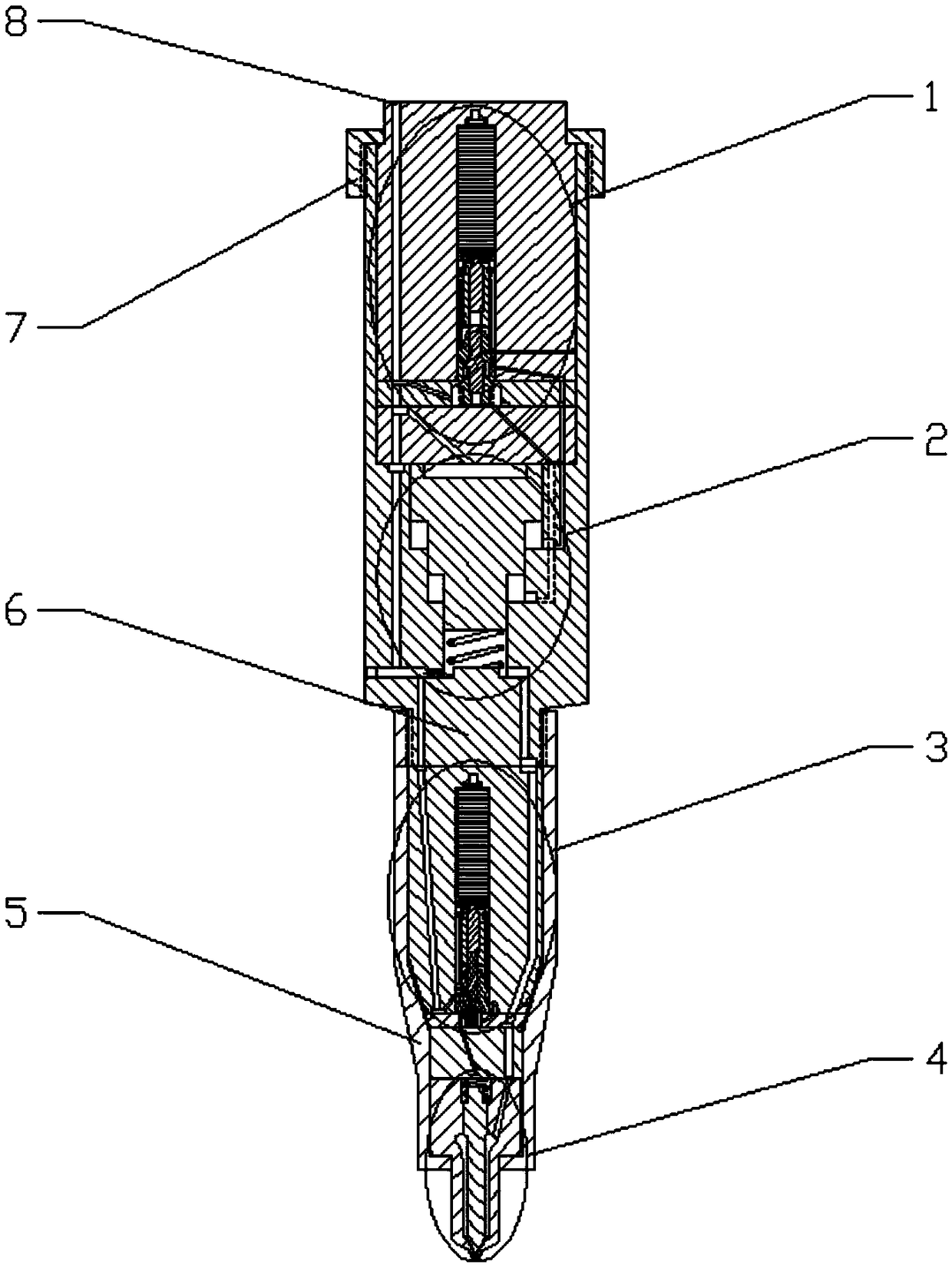
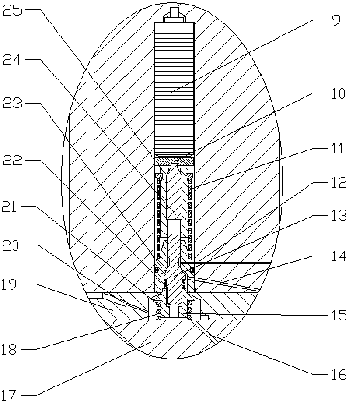
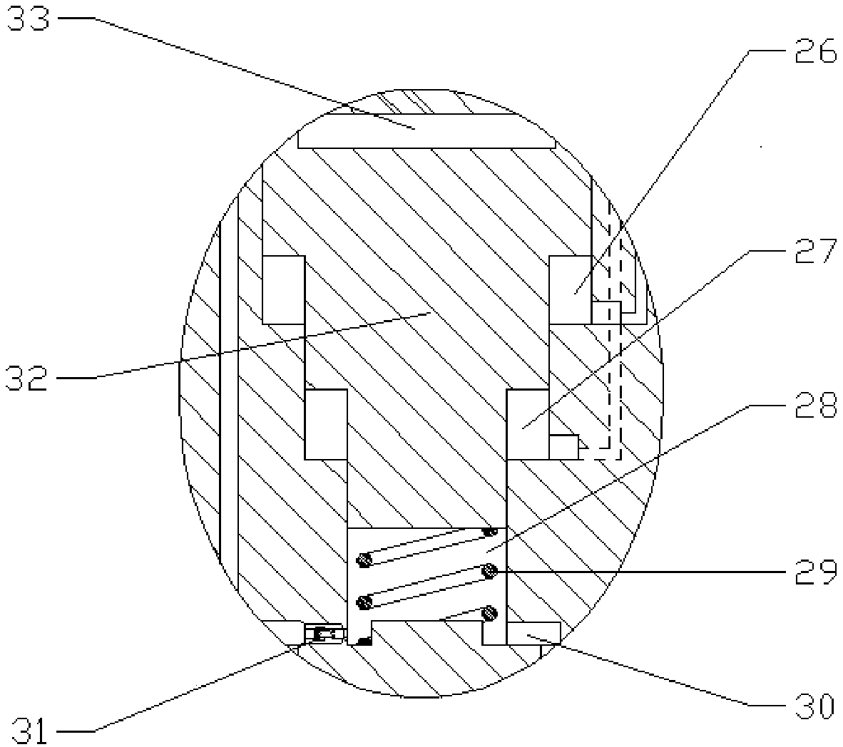
[0023] combine Figure 1-5 , the variable boost ratio piezoelectric fuel injector of the present invention is composed of a boost control valve part 1, a three-stage piston assembly 2, a fuel injection control valve part 3, a needle valve part 4, a nozzle tight cap 5 and a fuel injector body 6 composition. The boost control valve part 1 is mainly composed of a piezoelectric stack 9, a gasket 10, a plate spring 11, a boost control valve stem 13, a fungus sleeve 15, a fungus sleeve limiting orifice 19, a fungus Shape sleeve spring 21, boost control valve stem spring 22, boost control valve stem sleeve 23, hydraulic core 25 and hydraulic sleeve 24 are formed. There is a triangular fuel oil passage at the head of the valve stem 13 of the boost control valve, and the mushroom-shaped sleeve 15 is set on the head of the valve stem 13 of the boost control valve, which c...


PUM


Abstract

It is an object of the present invention to provide a variable-pressure-ratio piezoelectric fuel injector including a pressurizing control valve portion, a three-stage piston assembly, a fuel injection control valve portion, a needle valve portion, and a fuel injector body. The piezoelectric fuel injector uses a pressurizing control valve structure to control the pressurizing area of the three-stage piston, can effectively realize different pressure ratios, and makes a fuel injection law more flexible. The pressurizing control valve is driven by a piezoelectric stack so as to be positioned accordingly and accurately, and the adjustment speed of the pressurizing ratio of the pressurizing piston is increased and the control precision of the fuel injection law is improved. The operation process of the needle valve is driven by the piezoelectric stack. The needle valve is fast in respond speed and large in control freedom. The fuel injection law is flexible and controllable, and effectively improves the power property and the economical efficiency of a diesel engine, so that the diesel engine can meet more stringent emission regulations.

Description

technical field [0001] The invention relates to a diesel engine, in particular to a diesel engine fuel system. Background technique [0002] Due to the restriction of the fuel injection characteristics such as fuel injection timing, fuel injection pressure and fuel injection rate by the cam of the high-pressure fuel supply pump, the mechanical fuel injector has disadvantages such as inflexible fuel injection characteristics, slow response, and poor control accuracy of fuel injection volume. With the increasingly stringent emission regulations, it is difficult to further improve the economy and emission of the engine. Compared with the mechanical injector, the electromagnetic control injector applied to the electronic control fuel injection system of diesel engine has faster response speed, flexible and controllable fuel injection characteristics, and more precise control of fuel injection quantity. [0003] Due to the large cycle fuel injection volume of large and medium-si...

Claims


Application Information

Patent Timeline
Patent Type & Authority Applications(China)
IPC IPC(8): F02M51/06F02M61/10F02M61/16F02M63/00
CPCF02M51/0603F02M61/10F02M61/16F02M63/0026
Inventor 范立云付立洲董瑞邦白云姚崇
Owner HARBIN ENG UNIV
Why Eureka
Eureka Blog
Learn More