Multifunctional mini-type electric fan

A multi-function, electric fan technology, applied in the direction of collectors, electric vehicles, electrical components, etc., can solve the problems of unable to meet the needs of different users, unable to be used as a power bank, single function of electric fans, etc., to achieve more product functions Elemental, rich in appearance, and multi-functional effects

Inactive Publication Date: 2015-06-03
何志雄
View PDF5 Cites 7 Cited by
  • Summary
  • Abstract
  • Description
  • Claims
  • Application Information

AI Technical Summary

Problems solved by technology

[0002] At present, miniature electric fan is liked by people because of its convenience of carrying; Inside the fan cover, a battery and a circuit board are installed on the lower part of the housing. The battery supplies power to the circuit board, and the circuit board controls the rotation of the fan blades; however, the above-mentioned traditional miniature fans still have the following disadvantages: (1) Since the miniature electric fan is mostly used for carrying out, when the power of the battery is used up, the fan needs to be replaced before the fan can continue to work, which brings great inconvenience to the user; (2) due to the single function of the electric fan, only As a fan, if the user goes out to use it, it often needs other auxiliary functions, such as: it cannot be used as a power bank, etc. Therefore, the existing miniature electric fan has a single function and cannot meet the needs of different users; (3) Although there are some The micro electric fan uses a lithium battery (rechargeable) as a power source, but the lower part of the housing where the lithium battery is located is an integral structure that cannot be disassembled with the housing (that is, the charging part cannot be disassembled). Therefore, when charging, it is often necessary to Take the whole electric fan together for charging, which will cause some inconvenience to users

Method used


Image

  • Multifunctional mini-type electric fan
  • Multifunctional mini-type electric fan
  • Multifunctional mini-type electric fan

Examples


Embodiment Construction

[0025] The present invention will be further described below in conjunction with the accompanying drawings and embodiments.

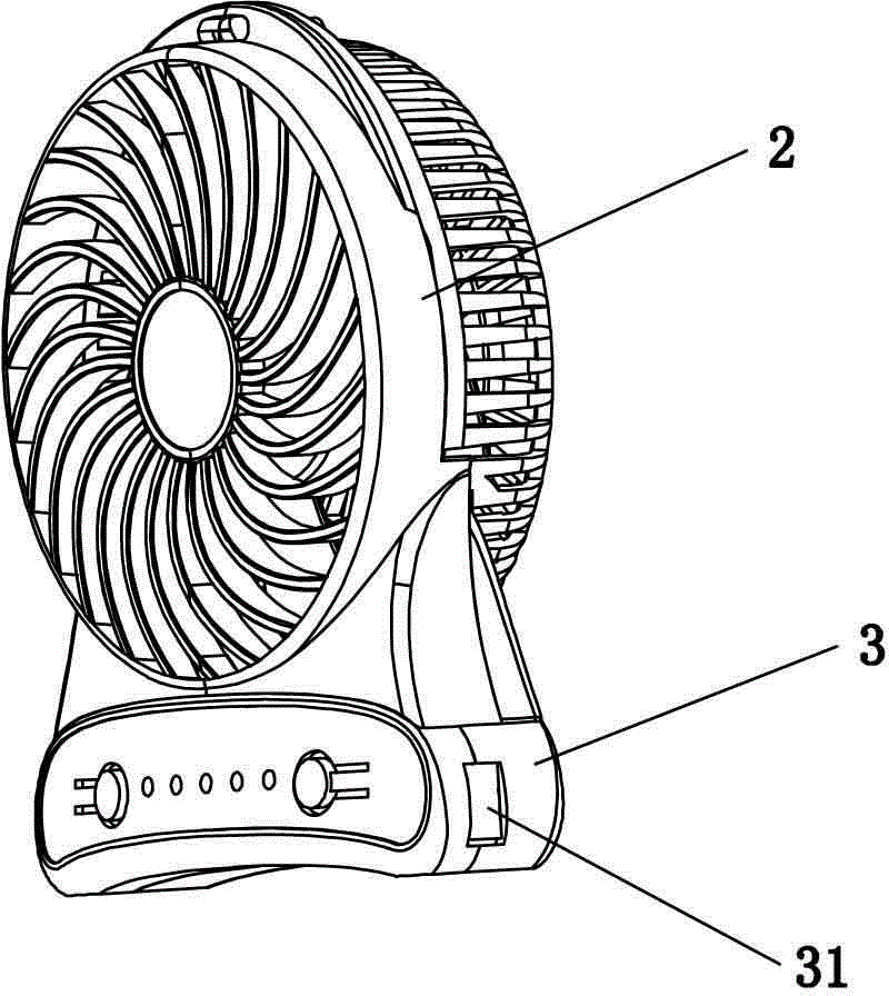
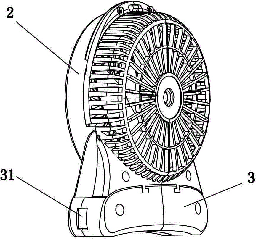
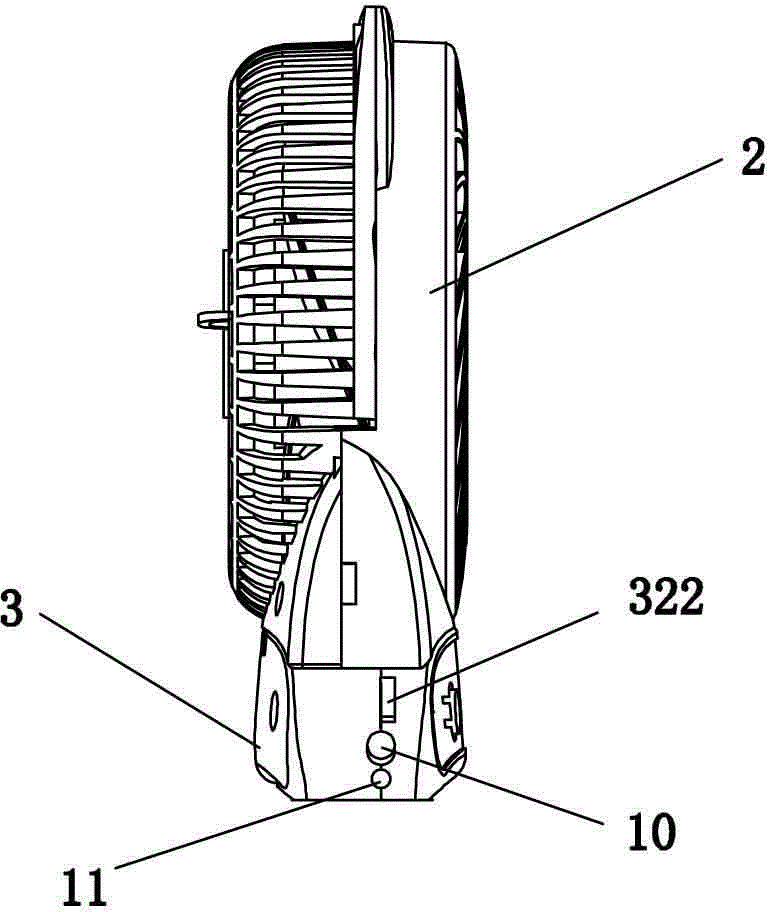
[0026] Such as Figure 1 to Figure 4 As shown, a multifunctional miniature electric fan includes a fan cover 2, fan blades 21 are arranged inside the fan cover 2, and the fan cover 2 is composed of left and right half-cases, and is characterized in that it also includes an independent charging Treasure 3 and power bank 3 are equipped with rechargeable battery 1, fan cover 2 is seated on power bank 3, and the connection between power bank 3 and fan cover 2 is detachable sliding rail chute type connection, so The contact surfaces of the fan cover 2 and the power bank 3 are respectively provided with conductive blocks 4 which are in contact with each other; 4 are electrically connected; and, the casing of the power bank 3 is composed of left and right charging half-shells spliced ​​together.

[0027] The bottom of the above-mentioned fan cover 2 is provi...


PUM


Abstract

The invention discloses a multifunctional mini-type electric fan. The multifunctional mini-type electric fan comprises a fan cover, wherein blades are arranged in the fan cover. The multifunctional mini-type electric fan is characterized by further comprising a charge pal, wherein the fan cover is arranged on the charge pal; the charge pal and the fan cover are connected and matched in a detachable slide rail and slide groove manner; conductive lumps which are in contact with each other are further arranged on the contact surfaces of the fan cover and the charge pal. According to the mini-type electric fan, the charge pal is simple to detach, and can be charged to provide a power supply to the blades, and also can provide the power supply to other current-using equipment, so that the multifunctional mini-type electric fan has many functions; the slide rail and slide groove type charge pal is in detachable connection and match with the fan cover so that the whole structure of the product is simple and reasonable, and the product is convenient to charge and use.

Description

technical field [0001] The invention relates to the technical field of miniature electric fans, in particular to a portable multifunctional miniature electric fan. Background technique [0002] At present, miniature electric fan is liked by people because of its convenience of carrying; Inside the fan cover, a battery and a circuit board are installed on the lower part of the housing. The battery supplies power to the circuit board, and the circuit board controls the rotation of the fan blades; however, the above-mentioned traditional miniature fans still have the following disadvantages: (1) Since the miniature electric fan is mostly used for carrying out, when the power of the battery is used up, the fan needs to be replaced before the fan can continue to work, which brings great inconvenience to the user; (2) due to the single function of the electric fan, only As a fan, if the user goes out to use it, it often needs other auxiliary functions, such as: it cannot be used ...

Claims


Application Information

Patent Timeline
Patent Type & Authority Applications(China)
IPC IPC(8): F04D25/08F04D29/00F04D29/40H02J7/00
CPCF04D25/08F04D29/002F04D29/522H02J7/00
Inventor 何志雄
Owner 何志雄
Why Eureka
Try Eureka