
Heat dissipation substrate

A technology of heat dissipation substrate and heat dissipation block, which is applied in heat transfer modification, heat exchange equipment, indirect heat exchanger, etc. Effect

Inactive Publication Date: 2015-06-03
SUBTRON TECH
View PDF5 Cites 5 Cited by
  • Summary
  • Abstract
  • Description
  • Claims
  • Application Information

AI Technical Summary

Problems solved by technology

[0003] The purpose of the present invention is to provide a heat dissipation substrate, which can solve the existing problem that the overall thickness of the heat dissipation substrate is thicker due to the addition of heat dissipation fins

Method used


Image

  • Heat dissipation substrate
  • Heat dissipation substrate
  • Heat dissipation substrate

Examples


Embodiment Construction

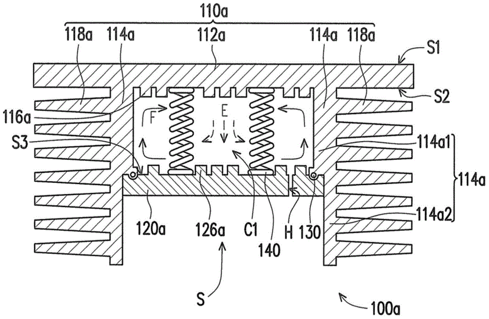
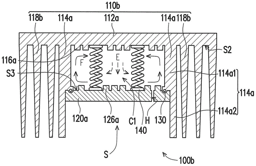
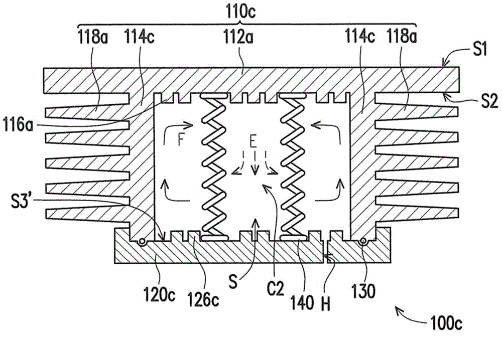
[0051] figure 1 A schematic cross-sectional view of a heat dissipation substrate according to an embodiment of the present invention is shown. Please refer to figure 1 , in this embodiment, the heat dissipation substrate 100a includes a heat dissipation block 110a, a metal substrate 120a and at least one elastic structure 140 ( figure 1 Two are schematically shown in ). The heat dissipation block 110a includes a carrying portion 112a and a plurality of supporting portions 114a. The carrying portion 112a has a carrying surface S1 and a lower surface S2 facing each other. The supporting portions 114a are parallel to each other and disposed on the lower surface S2 of the bearing portion 112a. The support portions 114a are vertical to the carrying portion 112a and surround the carrying portion 112a to form an accommodating space S. Referring to FIG. The carrying portion 112a has a first rough surface structure 116a on a portion of the lower surface S2, and the first rough sur...


PUM


Abstract

A heat dissipation substrate includes a heat sink, a metal base and an elastic structure. The heat sink includes a carrying portion and supporting portions. The supporting portions are parallel to one another and disposed on a lower surface of the carrying portion. The supporting portions are perpendicular to the carrying portion and surround an accommodating space with the carrying portion. The carrying portion has first rough surface structure disposed on a portion of the lower surface and located in the accommodating space. The metal base is disposed below the heat sink and has an assemble surface and a second rough surface structure disposed on a portion of the assemble surface and corresponding to the first rough surface structure. The first and second rough surface structures and the supporting portions define a fluid chamber in which the elastic structure is disposed, and a working fluid flows in the fluid chamber.

Description

technical field [0001] The invention relates to a heat dissipation substrate, and in particular to a heat dissipation substrate suitable for carrying at least one heating element. Background technique [0002] Generally speaking, in order to improve the heat dissipation effect of a vapor chamber, heat dissipation fins are usually added to the vapor chamber with a fixed fluid chamber to form a so-called heat dissipation substrate. Since the overall thickness of the above heat dissipation substrate is the thickness of the vapor chamber plus the thickness of the heat dissipation fins, compared with the thickness of a single vapor chamber, the thickness of the heat dissipation substrate is significantly increased, so it cannot meet the requirements of thin and short trend. Contents of the invention [0003] The purpose of the present invention is to provide a heat dissipation substrate, which can solve the existing problem that the overall heat dissipation substrate is thicke...

Claims


Application Information

Patent Timeline
Patent Type & Authority Applications(China)
IPC IPC(8): F28D15/04
CPCF28D15/0233F28D15/04F28F3/02F28F3/12F28F13/00F28F2255/02
Inventor 陈庆盛
Owner SUBTRON TECH
Learn More