Eddy radar defect detecting, quantifying and imaging method and system

A defect detection and imaging method technology, applied in the fields of material characterization and evaluation, equipment non-destructive testing, structural health monitoring and product quality control, which can solve problems such as poor anti-interference, low signal-to-noise ratio, and difficulty in judging distances.

Inactive Publication Date: 2015-06-03
WUXI DOUBLE HORSE DRILLING TOOLS
View PDF8 Cites 9 Cited by
  • Summary
  • Abstract
  • Description
  • Claims
  • Application Information

AI Technical Summary

Problems solved by technology

[0007] The current eddy current testing technology also has some deficiencies, mainly in: 1) The signal-to-noise ratio of the signal is low due to the influence of electromagnetic field attenuation and noise interference; 2) The quantitative accuracy of the depth of internal defects is not high, and it is difficult to judge the distance between defects 3) The C-scan imaging mainly relies on the time-domain eigenvalue and the position of the detection point, and the anti-interference is poor

Method used


Image

  • Eddy radar defect detecting, quantifying and imaging method and system
  • Eddy radar defect detecting, quantifying and imaging method and system
  • Eddy radar defect detecting, quantifying and imaging method and system

Examples


Embodiment Construction

[0056] The specific embodiments of the present invention are described below with reference to the accompanying drawings, so that those skilled in the art can better understand the present invention.

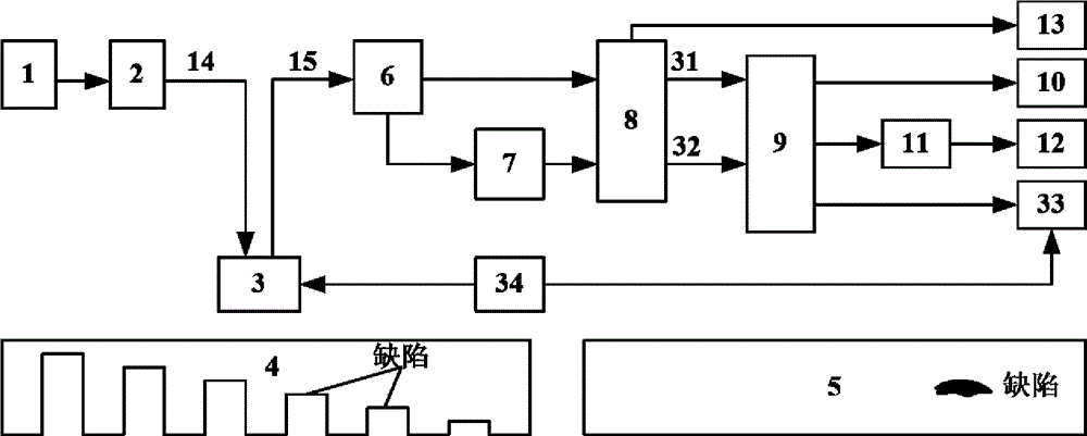
[0057] figure 1 It is a schematic diagram of an eddy current radar defect detection, quantification and imaging system, which mainly includes: human-machine interface 1, excitation signal module 2, eddy current sensor 3, standard specimen 4, tested object 5, signal conditioning module 6, reference signal setting Module 7 , signal processing module 8 , feature value extraction module 9 , defect detection module 10 , quantitative relationship determination module 11 , defect quantitative module 12 , B-scan imaging module 13 , C-scan imaging module 33 , and scanning mechanism 34 .

[0058] The specific implementation steps of an eddy current radar defect detection, quantification and imaging method based on an eddy current radar defect detection, quantification and imaging system ...


PUM


Abstract

The invention discloses an eddy radar defect detecting, quantifying and imaging method and system. According to the method, excitation signals in different modes such as pulse, sine, frequency modulation and phase modulation are adopted to excite a signal driving eddy sensor, and eddy can be sensed in a detected object. An output signal of the eddy sensor is taken as a time domain response signal, and the time domain response signal of an area free from defects is taken as a reference signal. A cross-correlation algorithm is applied to the time domain response signal and the reference signal, so that a cross-correlation amplitude value and phase can be obtained. Characteristic values for defect detection can be extracted from the cross-correlation amplitude value and the phase; through standard test piece experiment, a quantitative corresponding relationship of the characteristic value and the depth can be established, and quantification of the defect depth can be achieved; the cross-correlation amplitude value and the phase of each detection point on a scanning route can be displayed, and B-scanning imaging can be achieved; a scanning mechanism is adopted to detect one area, and the characteristic values are adopted for C-scanning imaging. The method and the system have the advantages of high signal to noise ratio, accurate depth quantification, good interference resistance, and the like, and can be applied to the field of nondestructive detection.

Description

technical field [0001] The invention belongs to the technical fields of equipment nondestructive testing, material characterization evaluation, structural health monitoring, product quality control and the like, in particular to an eddy current electromagnetic nondestructive testing method and system. Background technique [0002] With the development of modern science and industrial technology, non-destructive testing technology has become a necessary means to ensure product quality and equipment operation safety. At present, the representative non-destructive testing technologies mainly include radiographic testing, ultrasonic testing, penetrant testing, magnetic particle testing, Eddy Current Testing (ECT), as well as the rapidly developing thermal imaging testing, dislocation speckle interference and other technologies. [0003] Eddy current testing technology is a non-destructive testing method based on the principle of electromagnetic induction, which is suitable for c...

Claims


Application Information

Patent Timeline
Patent Type & Authority Applications(China)
IPC IPC(8): G01N27/90G01N27/9013
Inventor 何赟泽杨瑞珍
Owner WUXI DOUBLE HORSE DRILLING TOOLS
Why Eureka
Try Eureka