Improved non-contact transformer with secondary side current phase detection function

A technology of phase detection and secondary current, applied in the direction of measuring current/voltage, transformer/inductor core, transformer/inductor coil/winding/connection, etc., can solve the problem of system size reduction, reduce coupling coefficient, Simplify the circuit structure and reduce the effect of interference

Inactive Publication Date: 2015-06-03
NANJING UNIV OF AERONAUTICS & ASTRONAUTICS
View PDF11 Cites 9 Cited by
  • Summary
  • Abstract
  • Description
  • Claims
  • Application Information

AI Technical Summary

Problems solved by technology

Obviously, this is also not conducive to the reduction of system size

Method used


Image

  • Improved non-contact transformer with secondary side current phase detection function
  • Improved non-contact transformer with secondary side current phase detection function
  • Improved non-contact transformer with secondary side current phase detection function

Examples


Embodiment 1

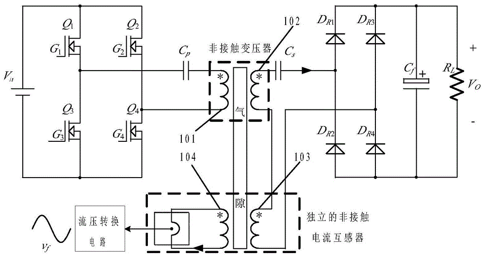
[0050] attached Picture 1-1 A full-bridge application circuit of an existing non-contact transformer plus an independent non-contact current transformer is given, wherein 101 is the primary side of the non-contact transformer, 102 is the secondary side of the non-contact transformer, and 103 is the excitation side of the non-contact current transformer. 104 is the test side of the non-contact current transformer, and 103 and 104 constitute an independent non-contact current transformer.

Embodiment 2

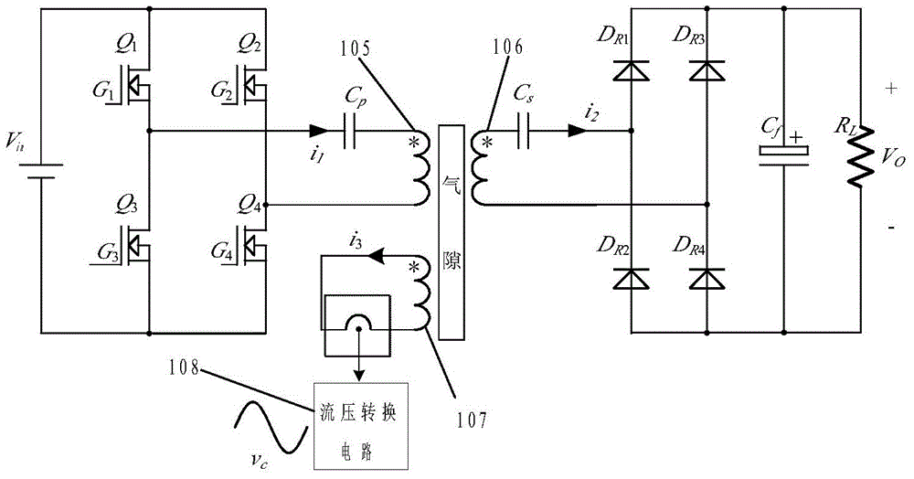
[0052] attached Figure 1-2 The full-bridge application circuit of the improved non-contact transformer of the present invention is given, compared Picture 1-1 with Figure 1-2 It can be seen that the improved non-contact transformer will not change the topology of the main circuit, where 105 is the primary winding, 106 is the secondary winding, 107 is the test winding, and 108 is the current-voltage conversion circuit.

Embodiment 3

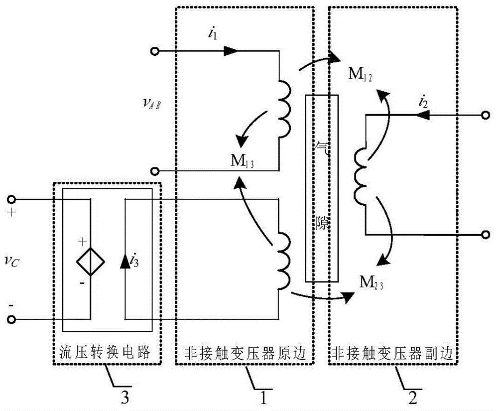
[0054] attached Figure 1-3 The structural block diagram of the improved non-contact transformer of the present invention is given, which is composed of the primary side 1 of the non-contact transformer, the secondary side 2 of the non-contact transformer and the current-voltage conversion circuit 3 .

[0055] The present invention designs that the primary side 1 of the non-contact transformer includes a primary magnetic core, a primary winding and a test winding. The test winding of the primary side 1 of the non-contact transformer is short-circuited (that is, shorted), and the primary winding can be connected in series or parallel by one winding or multiple windings. Combination composition.


PUM


Abstract

The invention provides an improved non-contact transformer with a secondary side current phase detection function. The non-contact transformer comprises a primary side and a secondary side; the primary side comprises a primary side magnetic core and a primary side winding; the secondary side comprises a secondary side magnetic core and a secondary side winding; the primary side also comprises a testing winding and a current voltage conversion circuit; the testing winding and the primary side winding share the primary side magnetic core; the testing winding is shortly connected; an output of the testing winding is switched into the current voltage conversion circuit. According to the invention, by reasonably designing the primary side winding and the testing winding, magnetic fluxes generated by currents of all parts of the primary side winding in all parts of the testing winding are partially or completely balanced out. By enabling the testing winding of the primary side of the non-contact transformer to be shorted out, a short-circuit current of the testing winding and a secondary side current always meet the linear relation under the conditions of loose coupling and a variable gap and in-phase voltage signals are obtained by the current voltage conversion circuit.

Description

technical field [0001] The invention relates to a non-contact transformer suitable for use in a non-contact energy transmission system, which belongs to the field of current transformers or electric energy conversion. Background technique [0002] Non-contact power supply is a new type of power transmission mode based on magnetic field coupling to realize "wireless power supply". It uses a non-contact transformer with completely separated primary and secondary sides to transmit power through high-frequency magnetic field coupling, so that the power transmission side (referred to as the power supply side) during the energy transfer process ) and the power receiving side (referred to as the power receiving side) have no physical connection. Compared with the traditional contact power supply, non-contact power supply is convenient and safe to use, without sparks and electric shock hazards, without dust accumulation and contact loss, without mechanical wear and corresponding mai...

Claims


Application Information

Patent Timeline
Patent Type & Authority Applications(China)
IPC IPC(8): H01F27/28H01F27/40H01F27/24G01R19/00
Inventor 徐立刚陈乾宏柯光洁任小永李明秋
Owner NANJING UNIV OF AERONAUTICS & ASTRONAUTICS
Why Eureka
Try Eureka