Supercharge Your Innovation With Domain-Expert AI Agents!

Beautified antenna mounted on overhead guardrail

A technology for beautifying antennas and guardrails, which is applied in the parts of lighting devices, antenna supports/installation devices, lighting devices, etc., can solve problems such as waste of resources, blowing down, damage to lamp poles, etc., to avoid repeated investment and reduce resources. Waste, the effect of increasing the contact area

Inactive Publication Date: 2015-06-03
杨沁航
View PDF7 Cites 1 Cited by
  • Summary
  • Abstract
  • Description
  • Claims
  • Application Information

AI Technical Summary

Problems solved by technology

[0002] Under the rapid development trend of today's urban landscape, network, lighting and video surveillance are required on ordinary roads, highways, streets and communities, and with the development and popularization of communication network technology, the layout network of antennas is becoming more and more complex , for a better environment, street lamp clusters are generally used to beautify the antenna, that is, the antenna for communication is installed on the lamp pole in the shape of a street lamp to meet the communication coverage needs of communication operators for roads and surrounding environments; at the same time, these places also need to set up video surveillance Camera to ensure safety. In order to meet the above requirements, the traditional design adopts a single setting. First, from the perspective of landscape, it cannot achieve a better fit with the surrounding environment; second, the video surveillance camera is not effective at night. Good; third, resulting in repeated investment in special poles, waste of resources and excessive damage to the surrounding overall landscape environment
In addition, the light pole is generally installed directly on the roadbed. Because the contact area between the light pole and the roadbed is small and the strength is not strong, the light pole will be damaged or blown down in case of strong wind or failure, affecting normal use.

Method used


Image

  • Beautified antenna mounted on overhead guardrail
  • Beautified antenna mounted on overhead guardrail
  • Beautified antenna mounted on overhead guardrail

Examples


Embodiment Construction

[0012] The following will clearly and completely describe the technical solutions in the embodiments of the present invention with reference to the accompanying drawings in the embodiments of the present invention. Obviously, the described embodiments are only some, not all, embodiments of the present invention. Based on the embodiments of the present invention, all other embodiments obtained by persons of ordinary skill in the art without making creative efforts belong to the protection scope of the present invention.

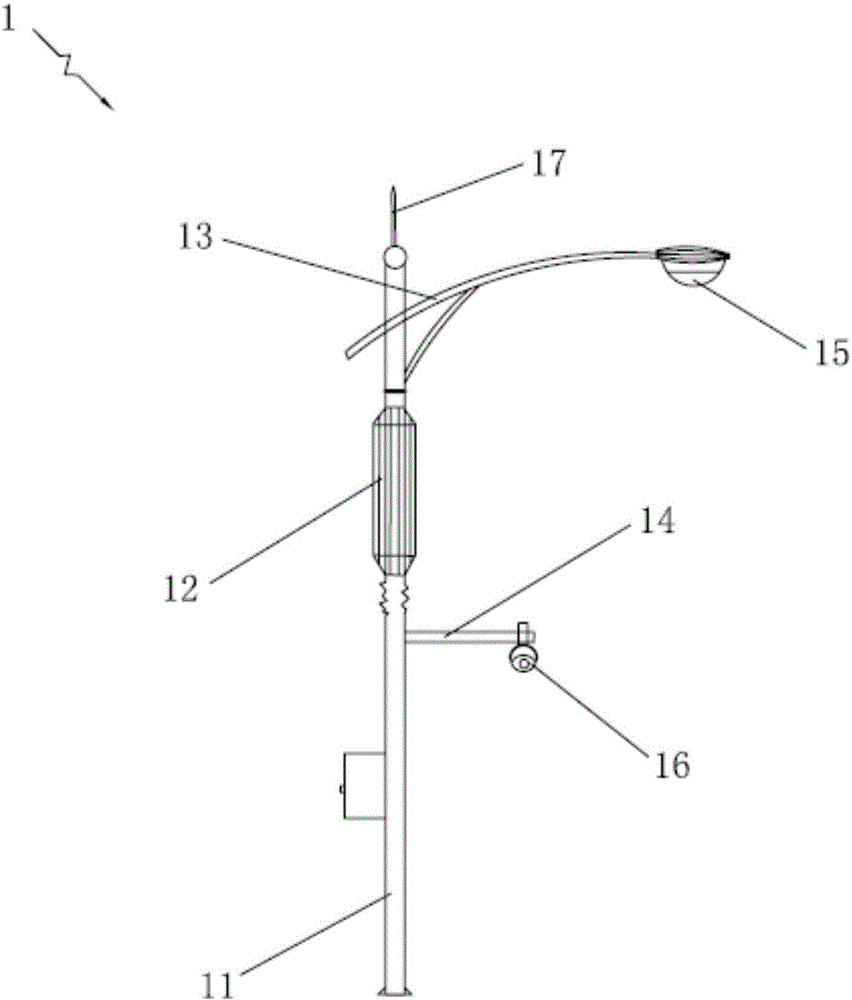
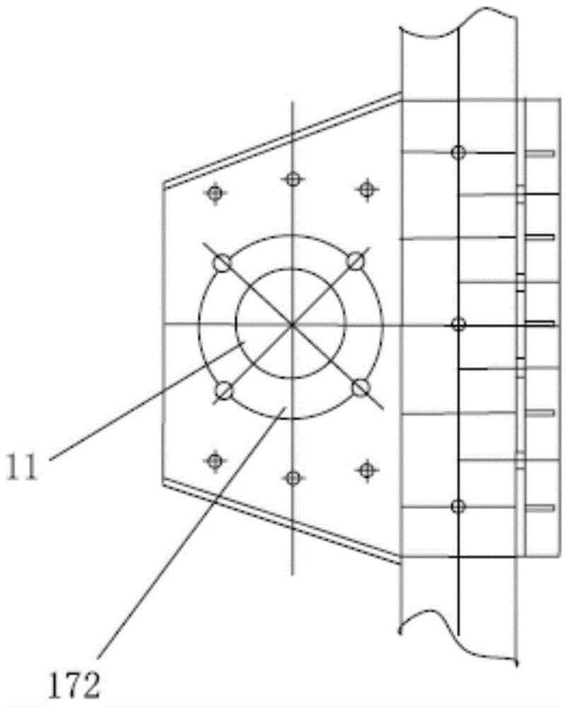
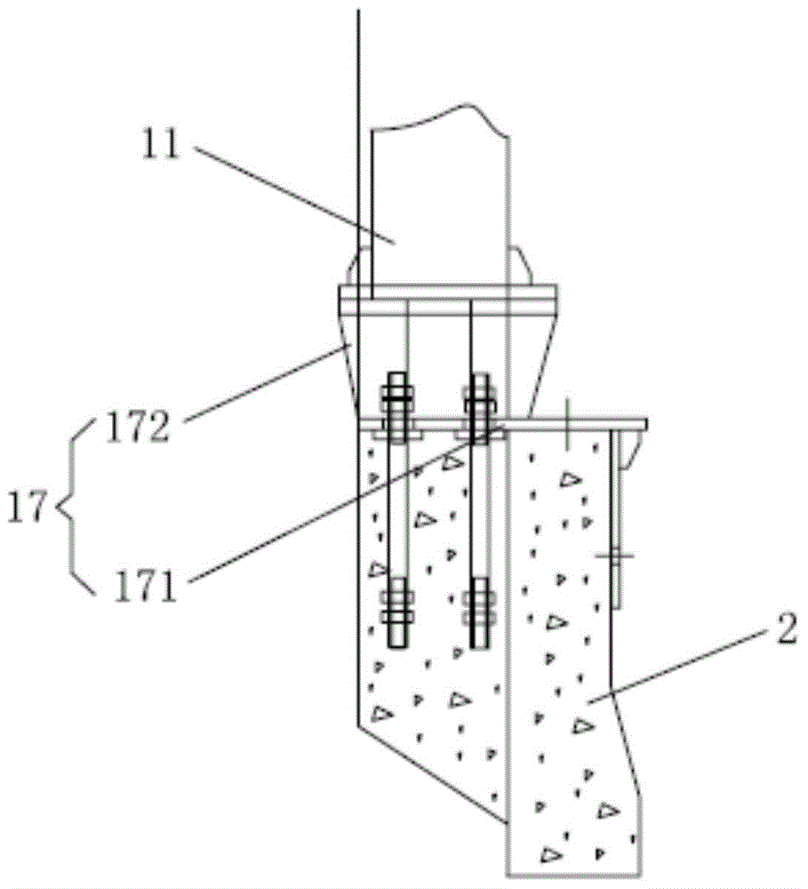
[0013] Such as Figure 1-Figure 3 , the embodiment of the present invention provides a beautification antenna 1 installed on the elevated guardrail, installed on the roadbed 2, the beautification antenna 1 includes a light pole 11, a pole 12 installed on the upper part of the light pole 11, and installed on the The street lamp bracket 13 on the upper part of the light pole 11 and the cross bar 14 installed in the middle of the light pole 11, a lamp cap 15 is i...


PUM


Abstract

The invention provides a beautified antenna mounted on an overhead guardrail, wherein a lamp holder is arranged at the end part of a street lamp support; a video monitor is arranged at the end part of a transverse rod; an antenna is arranged in a massive pillar; a lignting mounting position for daily lighting devices and a space for mounting a wireless communication coverage antenna can be reserved; meanwhile the mounting position of the video monitor is also integrated, so that under the condition of using the lighting function and video monitoring function at the same time, the shortage that a video monitoring camera cannot play the real monitoring role for the reason of poor light is overcome; the beautified antenna can fit with the surrounding environment better from the point of taking landscape into account, so that the repeated investments for special rods are avoided; a lamp pole is fixed on a roadbed by an adaptor; the adaptor comprises a mounting part which is fixed on the roadbed and a sleeve where the lamp pole is sleeved; the mounting part and the sleeve are formed integrally; the adaptor can increase the contacting area of the lamp pole, the strength is high, so that the lamp pole is not damaged or blown down in bad weather like strong wind and heavy rain.

Description

technical field [0001] The invention relates to the technical field of road public facilities, in particular to a beautifying antenna installed on an elevated guardrail. Background technique [0002] Under the rapid development trend of today's urban landscape, network, lighting and video surveillance are required on ordinary roads, highways, streets and communities, and with the development and popularization of communication network technology, the layout network of antennas is becoming more and more complex , for a better environment, street lamp clusters are generally used to beautify the antenna, that is, the antenna for communication is installed on the lamp pole in the shape of a street lamp to meet the communication coverage needs of communication operators for roads and surrounding environments; at the same time, these places also need to set up video surveillance Camera to ensure safety. In order to meet the above requirements, the traditional design adopts a singl...

Claims


Application Information

Patent Timeline
Patent Type & Authority Applications(China)
IPC IPC(8): H01Q1/22F21V21/108F21V23/00
Inventor 杨沁航
Owner 杨沁航
Features
  • R&D
  • Intellectual Property
  • Life Sciences
  • Materials
  • Tech Scout
  • Unparalleled Data Quality
  • Higher Quality Content
  • 60% Fewer Hallucinations
Learn More