Eureka AIR delivers breakthrough ideas for toughest innovation challenges, trusted by R&D personnel around the world.

Double-stator axial magnetic field motor

An axial magnetic field and dual stator technology, which is applied in electrical components, electromechanical devices, etc., can solve the problems of difficulty in current control of dual stator axial magnetic field motors, reduce the difficulty of current control, increase torque density, and achieve structural design. flexible effects

Inactive Publication Date: 2015-06-03
GUANGDONG WELLING ELECTRIC MACHINE MFG +1
View PDF5 Cites 15 Cited by
  • Summary
  • Abstract
  • Description
  • Claims
  • Application Information

AI Technical Summary

Problems solved by technology

[0006] The purpose of the present invention is to overcome the deficiencies of the above-mentioned prior art, and provide a double-stator axial field motor, which solves the pro

Method used


Image

  • Double-stator axial magnetic field motor
  • Double-stator axial magnetic field motor
  • Double-stator axial magnetic field motor

Examples


Embodiment 1

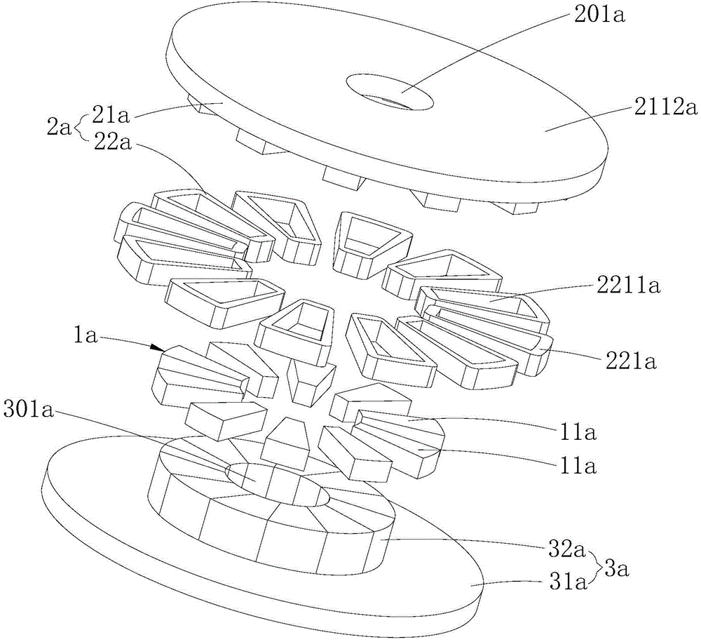
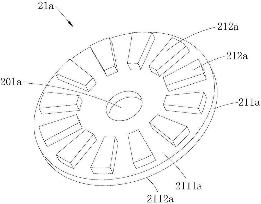
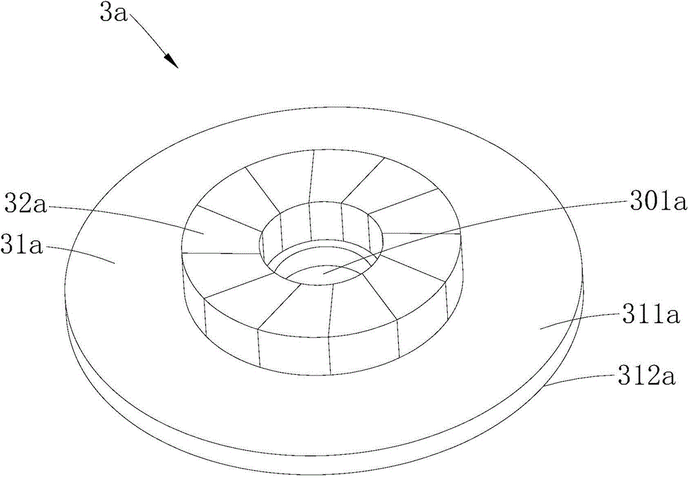
[0026] Such as Figure 1~3 As shown, the double-stator axial field motor provided by Embodiment 1 of the present invention includes a rotor 1a, an armature stator 2a arranged on one axial side of the rotor 1a, and an excitation stator 3a arranged on the other axial side of the rotor 1a The armature stator 2a includes an armature core 21a and an armature winding 22a disposed on the armature core 21a, and the field stator 3a includes a field core 31a and several magnetic poles 32a protruding from the field core 31a. The control current of the armature stator 2a is an alternating current, and no control current is set on the excitation stator 3a (the excitation stator 3a adopts permanent magnet excitation), that is, the input current of the armature winding 22a is an alternating current, and no input current is set on the magnetic pole 32a In this way, since the control currents of the armature stator 2a and the excitation stator 3a are different, it effectively reduces the diffi...

Embodiment 2

[0041] Such as Figure 4 As shown, the same as Embodiment 1, the dual-stator axial field motor provided in this embodiment also includes a rotor 1b, an armature stator 2b disposed on one axial side of the rotor 1b, and an axial stator 2b disposed on the axial side of the rotor 1b. The field stator 3b on the other side, the armature stator 2b includes the armature iron core 21b and the armature winding 22b arranged on the armature iron core 21b, the field stator 3b includes the field core 31b and a number of protrudingly arranged on the field core The magnetic pole 32b on the 31b; and the main difference between this embodiment and the first embodiment is the design of the excitation stator 3b, which is embodied in that the magnetic pole 32a in the first embodiment is a permanent magnet located on the excitation core 31a, and the excitation The stator 3a does not need to input control current during the working process; and in this embodiment, the magnetic pole 32b includes the...


PUM


Abstract

The invention is applied to the field of motors, and discloses a double-stator axial magnetic field motor. The double-stator axial magnetic field motor comprises a rotor, an armature stator arranged on the axial side of the rotor, and a magnet exciting stator arranged on the other axial side of the rotor, wherein the armature stator comprises an armature core and an armature winding arranged on the armature core; the magnet exciting stator comprises a magnet exciting core and a plurality of magnetic poles convexly arranged on the magnet exciting core. By setting two stators on the two sides of the rotor as the armature stator and the magnet exciting stator, the double-stator axial magnetic field motor ensures that control current of the two stators on the two sides of the rotor is not the same, further reduces the current control difficulty of the motor; in addition, as the magnet exciting stator can produce magnet exciting field during the operation of the motor, counter electromotive force can be produced in the armature winding during the rotation of the rotor, the counter electromotive force can be applied to alternating armature current on the armature stator, so as to produce power and torque, and the torque density of the double-stator axial magnetic field motor is further increased.

Description

technical field [0001] The invention belongs to the field of motors, in particular to a double-stator axial field motor. Background technique [0002] Most of the traditional double-stator motors are double-stator radial field motors. When the number of poles of the double-stator motor is large and the ratio of the axial length to the outer diameter of the double-stator motor is small, the efficiency of the double-stator radial field motor will be low, The unit output torque is small. [0003] In order to overcome the shortcomings of the above-mentioned traditional double-stator radial field motor, a design scheme of a double-stator axial field motor is proposed in the prior art. Compared with the double-stator radial field motor, when the number of poles of the double-stator motor is large enough and the ratio of the axial length to the outer diameter is small enough, the double-stator axial field motor has obvious advantages in terms of efficiency and unit output torque ...

Claims


Application Information

Patent Timeline
IPC IPC(8): H02K16/04
CPCH02K16/04
Inventor 诸自强周严鉴陈金涛
Owner GUANGDONG WELLING ELECTRIC MACHINE MFG
Why Eureka
Eureka Blog
Learn More