Thermoplastic Containers

A thermoplastic material and container technology, applied in the direction of rigid containers, containers, and the arrangement combined with the fuel supply of internal combustion engines, can solve the problems of complex container weight, fuel leakage, etc.

Inactive Publication Date: 2017-07-25
KAUTEX TEXTRON
View PDF1 Cites 0 Cited by
  • Summary
  • Abstract
  • Description
  • Claims
  • Application Information

AI Technical Summary

Problems solved by technology

[0006] As an alternative to the variant described in DE 10 2010 036 683 A1, simpler variants of the support of the vessel wall with columnar reinforcing elements inside the vessel are known, but these elements all have the following disadvantages: because they Rigidity of the container wall, when there are accidental induced deformations of the container wall, they break through the container wall or cause the container wall to tear apart, allowing the fuel to escape
Known external reinforcements for containers are complex and at the expense of the weight of the container

Method used


Image

  • Thermoplastic Containers
  • Thermoplastic Containers
  • Thermoplastic Containers

Examples


Embodiment Construction

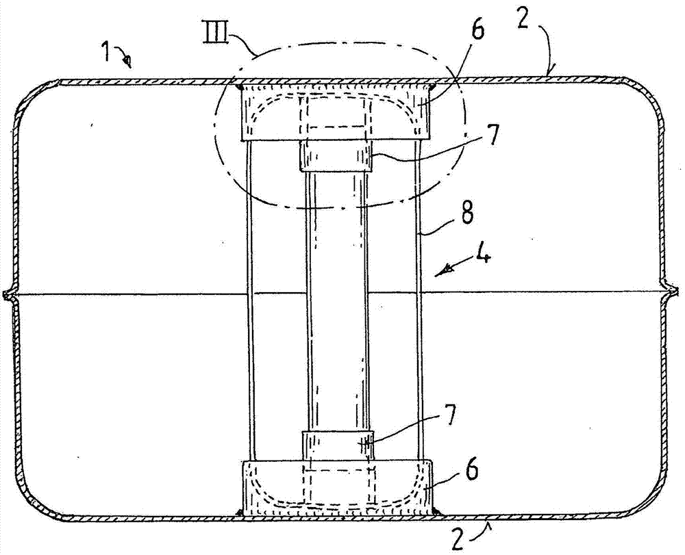
[0045] exist figure 2 In, a container 1 as provided by the invention is shown in section in greatly simplified form. The container 1 may for example be formed as an integrally formed extrusion blow molded fuel tank. This container comprises a container wall 2 enclosing a cavity 3 to be filled with liquid. The container wall 2 consists of a thermoplastic material, preferably a multilayer extrusion based on polyethylene.

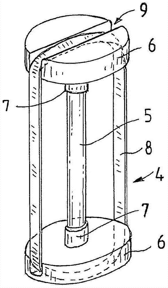
[0046] The large-area opposing regions of the container wall 2 , which have a relatively low moment of area area, are supported on one another by means of multipart supports 4 . The support 4 is in figure 1 is shown in perspective view.

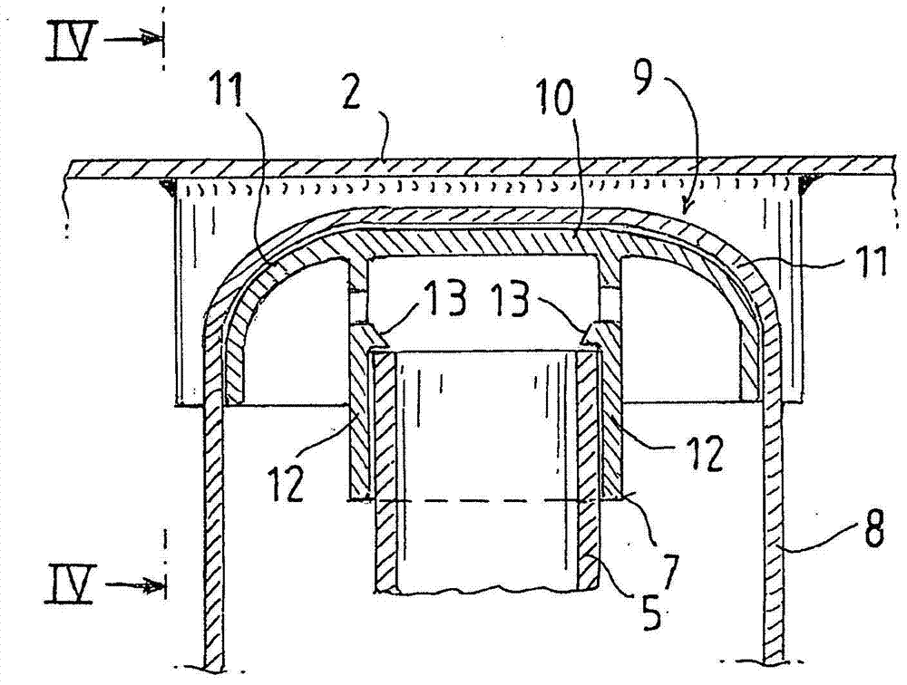
[0047] This support 4 comprises a support column 5 provided at each end with a base 6 of thermoplastic material, the plastic of which is compatible with the plastic of the container wall 2 in terms of weldability.

[0048] The base 6 fits onto the support column 5 at each end and engages or clips thereto. The support c...


PUM


Abstract

The invention relates to a container (1) of thermoplastic material having at least one support (4) arranged in the interior of said container, extending between opposite container walls (2) and at each end part is anchored to the container wall by positive engagement and / or material bonding, said support (4) comprises at least one support column (5) and said support column (5) substantially absorbs the forces caused by the negative pressure in the container Support loads on the container walls (2) and tensions caused by normal pressure are absorbed by at least one tension support element in the form of a tension-resistant band (8) extending between the container walls (2).

Description

technical field [0001] The invention relates to a container of thermoplastic material having at least one support arranged in the interior of the container, extending between opposite walls of the container and at each end by a form-fit (possitively engaging) and / or material bonding is anchored to the wall of the container, the support comprising at least one support column. Background technique [0002] Such a container is known, for example, from DE 10 2010 036 683 A1. DE 10 2010 036 683 A1 relates to a fuel tank having a cavity, arranged in which is a reinforcement for support, which is constructed such that it can absorb compressive and tensile forces. Provided for this purpose are tension compression struts which are arranged between two opposing wall regions of the fuel tank and respectively pass through the walls of the fuel tank. The tension-compression column is supported by spring means between two opposing wall members of the fuel tank; the opposing wall members...

Claims


Application Information

Patent Timeline
Patent Type & Authority Patents(China)
IPC IPC(8): B60K15/03B29C65/56B29C65/00B29C49/04B29C49/20B29C65/02B29C51/12B29C51/00
CPCB60K2015/03467B29C66/1312B29C66/532B29C66/54B29C66/61B29C2049/2013B60K2015/03032B60K2015/03453B60K2015/0346B29L2031/7172B29C49/04B29C65/02B60K15/03177B65D11/22B65D25/24B65D43/00B29C49/20B29K2023/065
Inventor T·海德迈尔U·卡尔施S·伦茨F·匡特T·瓦格纳
Owner KAUTEX TEXTRON
Why Eureka
Try Eureka