
Pinch follow-up mechanism of bending machine

A technology of a follower mechanism and a bending machine, which is applied in the field of bending machines, can solve the problems of single function and complex structure of the follower mechanism, and achieves the effect of convenient bending work and simple structure.

Active Publication Date: 2017-01-04
OMS MASCH CO LTD
View PDF4 Cites 0 Cited by
  • Summary
  • Abstract
  • Description
  • Claims
  • Application Information

AI Technical Summary

Problems solved by technology

[0004] In the bending process of the heat exchanger, the existing bending machine generally needs to be equipped with a follower mechanism that can be dragged by the heat exchanger to carry the heat exchanger. The existing follower mechanism has a complex structure and a single function

Method used


Image

  • Pinch follow-up mechanism of bending machine
  • Pinch follow-up mechanism of bending machine
  • Pinch follow-up mechanism of bending machine

Examples


Embodiment Construction

[0010] The present invention will be further described in detail below in conjunction with the accompanying drawings and specific embodiments.

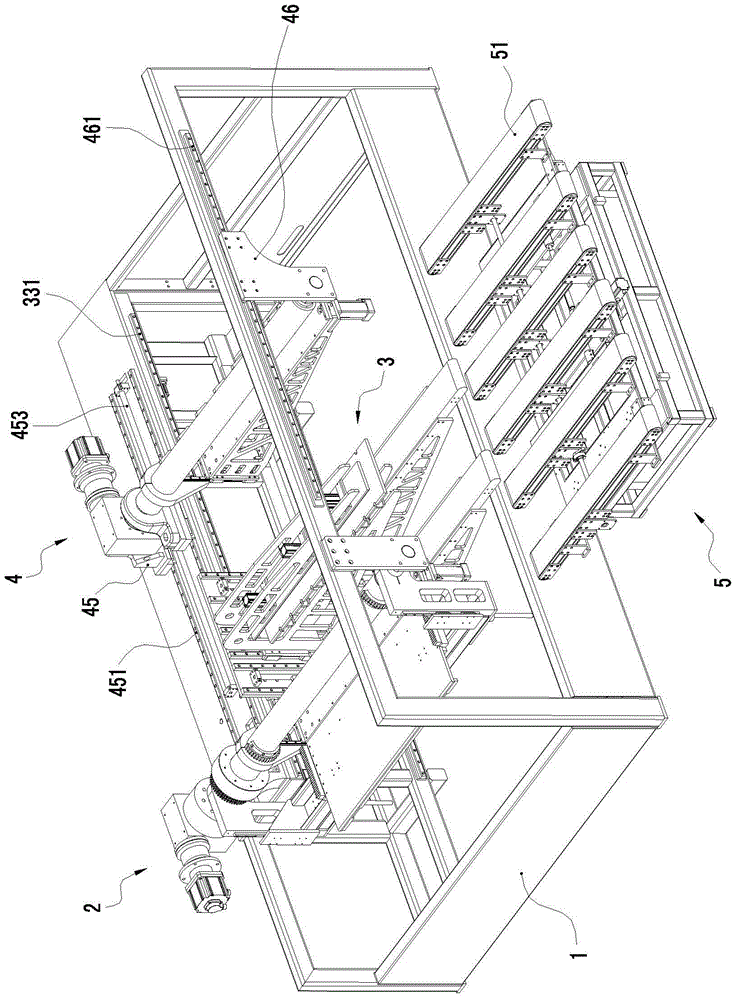
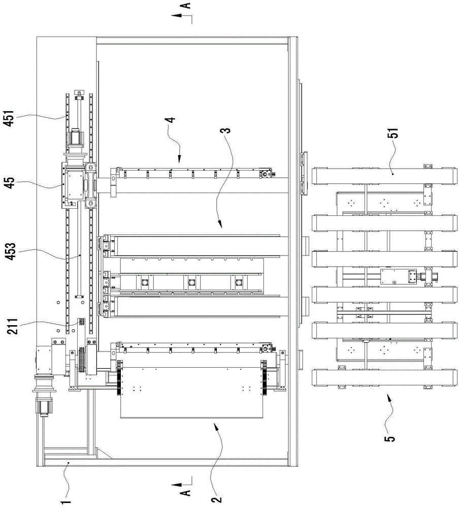
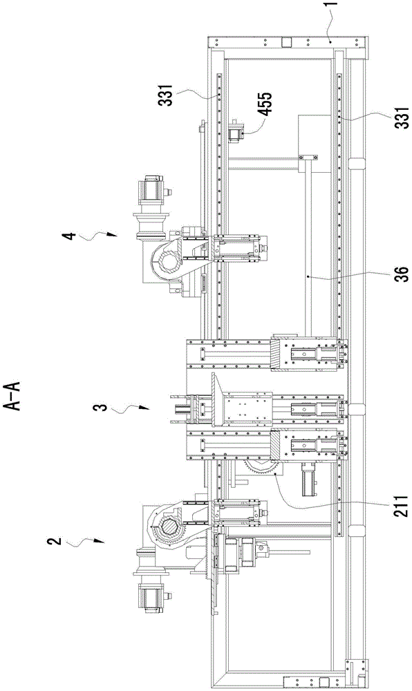
[0011] Such as Figure 1 to Figure 4 As shown, a bending machine includes a frame 1, a first bending mechanism 2 mounted on the frame 1 capable of bending the rear section of the workpiece, and a follower mechanism 3 mounted on the frame capable of carrying the workpiece , also includes a second bending mechanism 4 that is arranged on the frame 1 and can bend the front section of the workpiece, the follow-up mechanism 3 is located between the first bending mechanism 2 and the second bending mechanism 4 . When the workpiece is fed into the bending machine, the workpiece is fed along the transverse direction and enters the first bending mechanism 2, the follower mechanism 3 and the second bending mechanism 4 in sequence, and the workpiece can be sent into the bending machine through the automatic feeding equipment.

[0012] Such as F...


PUM


Abstract

The invention relates a clamping following mechanism for a bending machine. The clamping following mechanism comprises a frame, a clamping bracket, a clamping bracket sliding guiding mechanism, a clamping bracket sliding driving mechanism, a clutch device and a clamping following plate, wherein the clutch mechanism is arranged between the clamping bracket sliding driving mechanism and the clamping bracket, and optionally enables the clamping bracket sliding driving mechanism and the clamping bracket to be separated or connected to cut or convey the power input to the clamping bracket by the clamping bracket sliding driving mechanism; a material clamping plate is mounted on the clamping bracket above the clamping following plate; a material clamping plate lifting and driving mechanism driving the material clamping plate to be near to or far away from the clamping following plate to clamp or loosen a workpiece is arranged between the material clamping plate and the clamping bracket. The clamping following mechanism is simple in structure, can bear a workpiece and conduct following loading during a workpiece bending process on one hand, can actively clamp the workpiece to conduct adjustment of different positions before or after the bending of the workpiece, and brings convenience for bending work.

Description

technical field [0001] The invention relates to a bending machine, in particular to a pinch follow-up mechanism of the bending machine. Background technique [0002] As a compact heat exchanger, the tube-fin heat exchanger has a wide range of applications in the refrigeration industry. The forming process of the heat exchanger mainly includes the following three forming processes: tube bending forming (forming U-shaped tubes), mechanical expanding tube forming (realizing tube-fin connection), tube bundle bending forming (forming L-shaped or U-shaped or G-shaped Heat Exchanger). Tube bundle bending is one of the key processes in heat exchanger forming, which has an important impact on the performance of heat exchangers. [0003] When the tube bundle is bent and formed, the heat exchanger is first transported to the specified position, so that the part to be bent is close to the bending die (roller) with a predetermined bending radius, and then clamped on both sides of the b...

Claims


Application Information

Patent Timeline
Patent Type & Authority Patents(China)
IPC IPC(8): B21D7/00B21D7/16B21D43/00B21D53/06
CPCB21D43/04B21D53/06
Inventor 龙晓斌洪伟东张红娟
Owner OMS MASCH CO LTD
Learn More