Rotary chamfering device for anchor plates

A chamfering device, rotary technology, applied in the field of rotary anchor plate chamfering device, can solve problems such as low production efficiency, achieve the effects of improving production efficiency, avoiding repeated installation, and reducing labor intensity

Inactive Publication Date: 2015-06-10
柳州市桥厦科技发展有限公司
View PDF6 Cites 2 Cited by
  • Summary
  • Abstract
  • Description
  • Claims
  • Application Information

AI Technical Summary

Problems solved by technology

[0003] The object of the present invention is to provide a rotary anchor plate chamfering device, aiming at solving the problem of low production efficiency

Method used


Image

  • Rotary chamfering device for anchor plates
  • Rotary chamfering device for anchor plates

Examples


Embodiment Construction

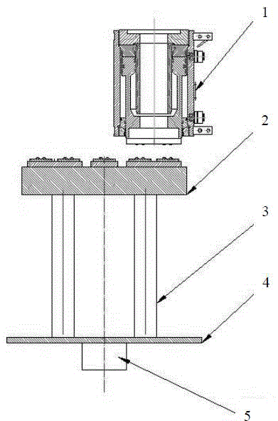
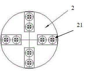
[0011] figure 1 Shows the overall structure diagram of a rotary anchor plate chamfering device provided by the present invention, the device mainly includes a punching device 1 and a workbench, the punching device 1 is a jack, and the workbench is mainly composed of a rotating disk tooling 2 , a strut 3, a chassis 4 and a rotating shaft 5 are combined, the lower end of the rotating disk tooling 2 is connected to the strut 3, the other end of the strut 3 is connected to the chassis 4, the lower end of the chassis 4 is provided with a rotating shaft 5, and the rotating The shaft 5 drives the chassis 4 to rotate, and the chassis 4 drives the rotary tooling 2 through the support rod 3. When chamfering, align the hole position of the working anchor plate with the protruding chamfering column on the rotary tooling 2 and place it. Extrude the tooling for chamfering; turn on the oil pump jack piston to extend down to pressurize the tooling, and the chamfering is completed. The piston...


PUM


Abstract

The invention relates to a stamping device, particularly to a rotary chamfering device for anchor plates. The device is mainly formed by combining a stamping device with a workbench, and the stamping device is a jack. By the aid of the device, multiple holes can be chamfered simultaneously by the aid of one action, a traditional chamfering method is changed, the production efficiency can be improved, meanwhile, repeated mounting and dismounting actions can be avoided, and the labor intensity of workers can be reduced to a certain extent.

Description

technical field [0001] The invention relates to the stamping field, and in particular belongs to a rotary anchor plate chamfering device. Background technique [0002] The stamping device in the prior art can only complete stamping once in one action, and then needs to be manually installed and removed repeatedly, which increases the labor intensity of workers and relatively reduces production efficiency. Contents of the invention [0003] The object of the present invention is to provide a rotary anchor plate chamfering device, aiming at solving the problem of low production efficiency. [0004] The present invention is achieved in this way, a rotary anchor plate chamfering device, the device is mainly composed of a punching device and a workbench, the punching device is a jack. [0005] A further technical solution of the present invention is: the workbench includes: a rotating disk tool, a support rod, a chassis and a rotating shaft, one end of the support rod supports...

Claims


Application Information

Patent Timeline
Patent Type & Authority Applications(China)
IPC IPC(8): B21D31/00
Inventor 罗盛敏黄湛李兰芬林贵宏
Owner 柳州市桥厦科技发展有限公司
Why Eureka
Try Eureka