
Plastic injection mould of domed plastic part

A technology for plastic parts and injection molds, which is applied in the field of injection molds for plastic domes, and can solve problems such as unstable jet flow in melt channels, poor surface quality of dome plastic parts, and failure to meet electroplating requirements, etc., to achieve good surface quality , prevent jet flow, avoid the effect of snake flow pattern

Inactive Publication Date: 2015-06-10
胡合红
View PDF2 Cites 0 Cited by
  • Summary
  • Abstract
  • Description
  • Claims
  • Application Information

AI Technical Summary

Problems solved by technology

In the injection mold for the above-mentioned dome plastic parts, the arrangement of the cavity and the location of the sprue are symmetrical in stress, which can prevent the mold from being subjected to eccentric loads and cause flashing, and the balance and workability are good. However, using the above-mentioned dome plastic The surface quality of the dome plastic parts made by the injection mold is very poor, and there are serious defects such as serpentine lines. This is because the depth of the sprue is much smaller than the depth of the cavity. When filling the film, the melt flow path It becomes an unstable jet flow. When the flowing melt in the back fills the cavity, the melt in the front has solidified, which leads to the appearance of serpentine lines, which cannot meet the requirements of electroplating.

Method used


Image

  • Plastic injection mould of domed plastic part
  • Plastic injection mould of domed plastic part
  • Plastic injection mould of domed plastic part

Examples


Embodiment Construction

[0013] The present invention is described below in conjunction with accompanying drawing.

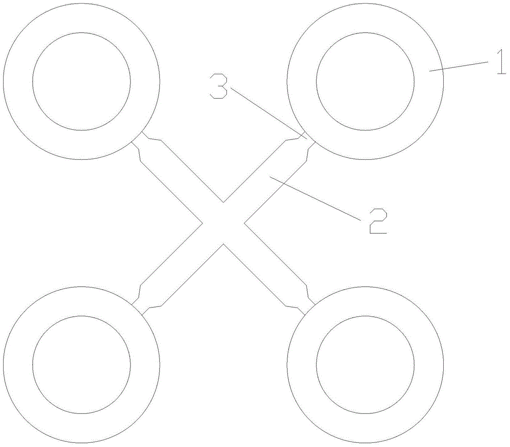
[0014] as attached Figure 4 A kind of dome plastic part injection mold of the present invention as shown, comprises dome plastic part mold cavity 1, runner 2 and sprue 3, and described dome plastic part mold cavity 1 is provided with four, and described The cavity 1 of the four dome plastic parts is arranged in a square, and the flow channel 2 communicates with the cavity 1 of the dome plastic part through the pouring port 3, and the flow channel 2 is in the shape of "H"; the shape of the "H" The four sprues 3 of the runner 2 are tangent to the circular wall at the bottom of the mold cavity 1 of the dome plastic part.

[0015] In the injection mold of the round cover plastic part of the present invention, since the flow channel is "H" type, the four spouts of the "H" type flow path are tangent to the circular wall at the bottom of the cavity of the round cover plastic part, and the sp...


PUM


Abstract

The invention discloses a plastic injection mould of a domed plastic part. The plastic injection mould comprises four domed plastic part cavities, a flow channel and pouring gates; the four domed plastic part cavities are arranged squarely; the flow channel is communicated with the domed plastic part cavities through the pouring gates; the flow channel is H-shaped; and four pouring gates of the H-shaped flow channel are tangent to the circular walls at the bottoms of the domed plastic part cavities. According to the plastic injection mould of the domed plastic part in the scheme provided by the invention, the flow channel is H-shaped; the four pouring gates of the H-shaped flow channel are tangent to the circular walls at the bottoms of the domed plastic part cavities; the pouring gates are arranged at the position closest to the cavity wall; in the event of flowing out from the pouring gates, a molten body is stopped by the cavity wall; generation of a jet flow can be prevented, so that an expansion flow is formed; S-shaped flow lines on the surface of the domed plastic part are avoided; and thus, the domed plastic part is good in surface quality, and can satisfy electroplating requirements.

Description

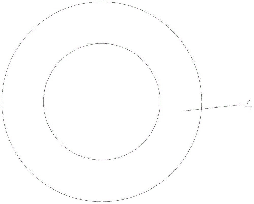
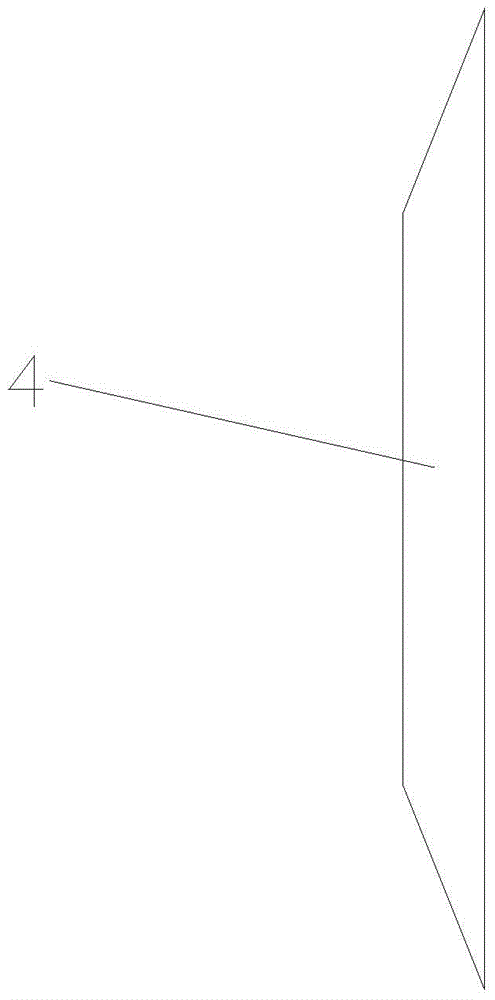
technical field [0001] The invention relates to an injection mold, in particular to an injection mold for a round cover plastic part. Background technique [0002] The shape of the plastic part 4 of the round cover is as attached figure 1 , 2 As shown, there are two specifications, large and small. Because the surface is to be electroplated, it is required to have a smooth surface and no defects such as gates and patterns. Existing dome plastic part injection mold, structure is as attached image 3 As shown, it includes the cavity 1 of the round cover plastic part, the runner 2 and the pouring port 3. There are four cavity 1 of the round cover plastic part, and the four cavity 1 of the round cover plastic part are arranged in a square, and the runner 2 passes The pouring port 3 communicates with the mold cavity 1 of the dome plastic part, and the runner 2 is "X" shaped, and the four pouring ports 3 of the "X"-shaped runner 2 are located in the radial direction of the dome...

Claims


Application Information

Patent Timeline
Patent Type & Authority Applications(China)
IPC IPC(8): B29C45/32B29C45/27
CPCB29C45/32B29C45/2735B29C45/322
Inventor 胡合红
Owner 胡合红
Learn More