Scraped-car fuel tank residual fuel recycling device and working method thereof

A recovery device and fuel tank technology, which is applied in the direction of vehicle scrap recovery, recycling technology, motor vehicles, etc., can solve the problems of complex fuel tank structure, low work efficiency, incomplete fuel recovery, etc., and achieve small footprint and automation The effect of high degree and good convenience

Active Publication Date: 2015-06-10
JIANGSU UNIV OF TECH
View PDF6 Cites 10 Cited by
  • Summary
  • Abstract
  • Description
  • Claims
  • Application Information

AI Technical Summary

Problems solved by technology

[0002] With the continuous development of my country's automobile industry, the number of scrapped cars is also increasing. When recycling and dismantling scrapped cars, in order to reduce the pollution of fuel to the environment and reduce the safety hazards in the dismantling of scrapped cars, fully To maximize the utilization value of the residual fuel in scrapped vehic...

Method used


Image

  • Scraped-car fuel tank residual fuel recycling device and working method thereof
  • Scraped-car fuel tank residual fuel recycling device and working method thereof
  • Scraped-car fuel tank residual fuel recycling device and working method thereof

Examples


Embodiment 1

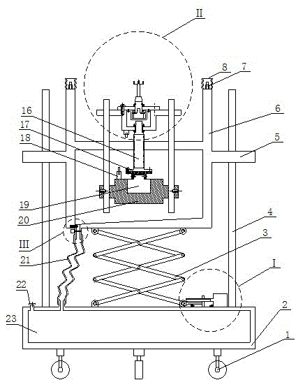
[0025] Such as figure 1 As shown, the present invention provides a fuel tank residual fuel recovery device, including: an oil receiving barrel 6, the oil receiving barrel 6 is provided with a drilling device for opening a hole at the bottom of the fuel tank, the drilling device is controlled by a The module controls the opening, and after the opening, the fuel remaining in the fuel tank flows into the oil receiving barrel 6 through the hole.

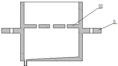
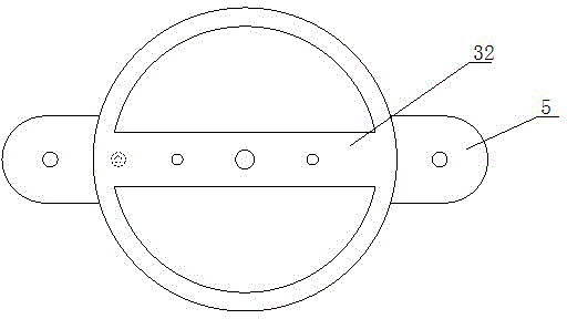
[0026] Such as diagram 2-1 with Figure 2-2 As shown, the oil receiving barrel 6 is a barrel-shaped part, with a semi-waist circular guide flange 5 on each side, and a guide hole (round shape is optional) in the middle of the guide flange, which can ensure oil connection In the direction of movement of the barrel 6, there is a long partition 32 in the oil barrel 6, and there is a guide hole (round shape can be selected) that matches with the drill lifting guide rod 10 on both sides of the partition 32. The hole can ensure the operating dir...

Embodiment 2

[0040] On the basis of Embodiment 1, the present invention also provides a working method of a fuel tank residual fuel recovery device, the fuel tank residual fuel recovery device includes: an oil barrel 6 and a drilling device controlled by a control module; The working method includes: the control module is adapted to make a hole in the bottom of the fuel tank through a drilling device, so that the remaining fuel in the fuel tank flows into the oil receiving barrel 6.

[0041] Specifically, the method in which the control module is adapted to make a hole in the bottom of the oil tank through a drilling device includes: the oil receiving barrel 6 controls the oil receiving barrel 6 to rise or descend through the oil receiving barrel 6 lifting mechanism, wherein when the oil receiving When the barrel 6 rises and the top touch switch 7 on the upper edge of the oil receiving barrel 6 is in contact with the bottom of the oil tank, the control module controls the drilling device to mo...


PUM


Abstract

The invention relates to a scraped-car fuel tank residual fuel recycling device and a working method thereof. The scraped-car fuel tank residual fuel recycling device comprises a fuel collection barrel, and a drilling device used for drilling a hole in the bottom of a fuel tank is arranged in the fuel collection barrel and is controlled by a control module. Residual fuel in the fuel tank flows into the fuel collection barrel via the hole after drilling. The scraped-car fuel tank residual fuel recycling device and the working method thereof have the advantages that the fuel recycling device is utilized for recycling the residual fuel of the fuel tank of a scraped car, so that safety and environment protection are achieved, and the residual fuel of the fuel tank of the scraped car can be recycled to the greatest extent; the fuel recycling device is high in automation degree, capable of achieving automated operation in the whole recycling process, time saving, labor saving, high in efficiency, small in occupied space, flexible to move and convenient for workshop layout and operation.

Description

Technical field [0001] The invention relates to a device for recovering residual fuel in a fuel tank of a scrapped automobile and a working method thereof. Background technique [0002] With the continuous development of China’s automobile industry, the number of scrapped automobiles is increasing. When scrapped automobiles are recycled and dismantled, in order to reduce the pollution of fuel to the environment, but also to reduce the potential safety hazards in the dismantling of scrapped automobiles. To make use of the value of the remaining fuel in scrapped cars, it is necessary to recover the remaining fuel in the fuel tank. At present, in China, professional scrapped car fuel tank residual fuel recovery devices have not yet appeared. The fuel tank remains in the fuel tank when scrapped cars are dismantled. The recovery of fuel is generally carried out by manual suction, which has low work efficiency, and due to the complex internal structure of the fuel tank, fuel recovery i...

Claims


Application Information

Patent Timeline
IPC IPC(8): B62D67/00
CPCY02W30/56B62D67/00
Inventor 蒋科军杭卫星李国庆蔡正松
Owner JIANGSU UNIV OF TECH
Why Eureka
Try Eureka