Rapid repair tower system and its erection method

A technology for repairing towers and towers, which is applied to towers, building types, buildings, etc., can solve problems such as power interruptions and delays in repairing time, and achieve the effects of improving installation efficiency, reducing costs, and facilitating transportation and assembly

Inactive Publication Date: 2017-11-10
HARBIN INST OF TECH
View PDF5 Cites 0 Cited by
  • Summary
  • Abstract
  • Description
  • Claims
  • Application Information

AI Technical Summary

Problems solved by technology

The quick repair tower is a standard section structure connected by bolts. The existing repair tower installation method is to assemble the standard section first and then transport it to the construction site, and use large hoisting equipment to erect the assembled emergency repair tower. The operation method is greatly affected by the terrain, especially in mountainous areas. If large cranes and other equipment cannot arrive in time or cannot reach the operation area, it will delay the repair time and cause long-term power interruptions.

Method used


Image

  • Rapid repair tower system and its erection method
  • Rapid repair tower system and its erection method
  • Rapid repair tower system and its erection method

Examples


Embodiment 1

[0055] Example 1, please refer to Figure 1 to Figure 6

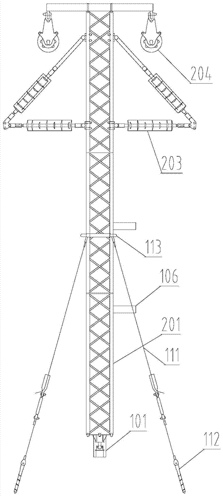
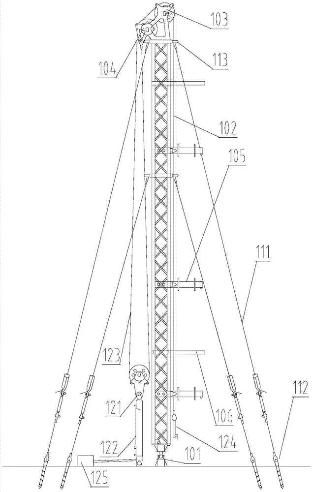
[0056] Such as Figure 1 to Figure 6 A quick repair tower system shown includes two bases 101, a repair tower and a lifting tower. The base 101 is arranged on a bottom plate fixed to the ground, and the repair tower and the lifting tower are respectively arranged on the two bases 101 In order to make the repair tower and the lifting tower and the base 101 more stable, in this embodiment, a support platform is provided under the repair tower and the lifting tower. The support platform is set on the base 101, and the support platform and the base 101 is fixedly connected, and the emergency repair tower and the lifting tower are vertically arranged on the supporting platform.

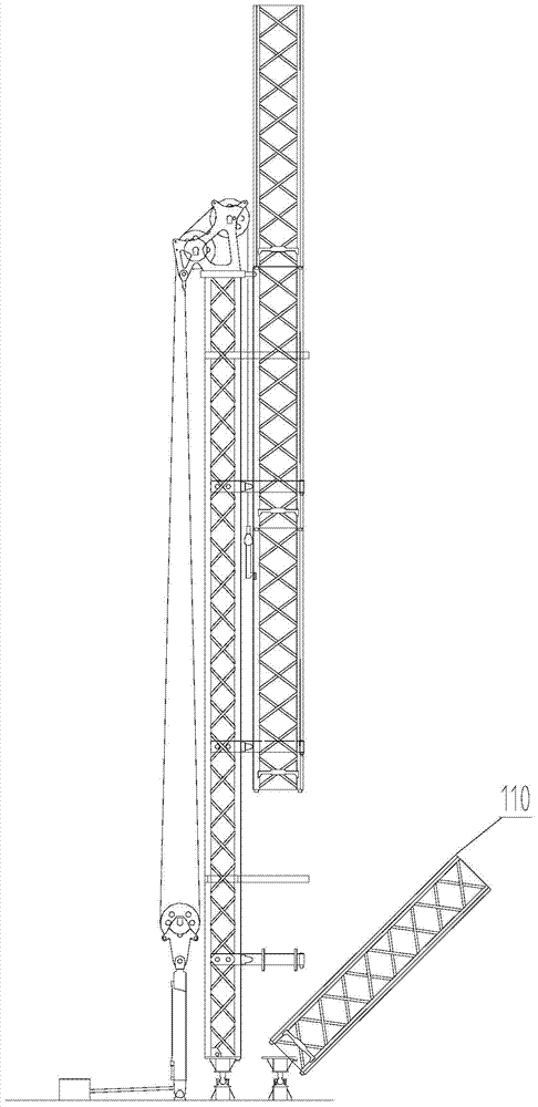
[0057] The repair tower includes a repair tower body 201, which includes a plurality of standard sections 110, a tower top hanger 204, and an insulator seat 203 connected in sequence, and the lower ends of the plurality of standard sections 110 connect...

Embodiment 2

[0089] Example 2, please refer to Figure 7 with Figure 8

[0090] The basic structure and principle of the rapid repair tower system provided in this embodiment and the technical effects produced are the same as those of the first embodiment. For a brief description, for the parts not mentioned in this embodiment, please refer to the corresponding content in the first embodiment.

[0091] The rapid repair tower system obtained through the above design can basically meet its normal use, but in the purpose of further improving its functions, the designer has further improved the rapid repair tower system.

[0092] The difference between this embodiment and Embodiment 1 is that the anchor cable device in this embodiment avoids the situation of insufficient pre-tightening force between the standard sections 110 when the anchor cable connecting frame 113 is fixed at the connection between the standard sections 110.

[0093] Further, the realization of the above-mentioned functions is real...


PUM


Abstract

The invention provides a rapid repairing tower system and an erection method thereof. The rapid repairing tower system is suitable for multiple topographies, and can be assembled rapidly. The rapid repairing tower system comprises two bases, a repairing tower and a lifting tower; each of the lifting and the repairing tower consists of multiple standard sections, which is detached and assembled conveniently. The repairing tower is installed by using the manner of adding the section on the bottom on the basis of the lifting tower, the installation of the repairing tower is completed without an additional lifting device, the installing speed is rapid, and the rapid repairing tower system is suitable for multiple topographies. The situation that the lifting device cannot be delivered to the installing area in time so as to cause the electricity interruption is avoided, and the electric power supply is effectively ensured.

Description

Technical field [0001] The invention relates to the field of power transmission equipment, and in particular to a rapid repair tower system and an erection method thereof. Background technique [0002] The emergency repair tower is a special tower used to temporarily restore power supply after a tower collapse accident occurs on a transmission line. The quick-installed emergency repair tower is a standard section structure that uses bolts. The existing emergency repair tower installation method is to assemble the standard section first and then transport it to the construction site. Use large hoisting equipment to erect the assembled emergency repair tower. The operation method is greatly affected by the terrain, especially in mountainous areas. Large cranes and other equipment cannot arrive in time or cannot reach the operation area, which will delay the repair time and cause long-term power interruption. Therefore, there is an urgent need for a rapid repair tower system that i...

Claims


Application Information

Patent Timeline
Patent Type & Authority Patents(China)
IPC IPC(8): E04H12/00E04H12/08E04H12/20E04H12/34
CPCE04H12/00E04H12/08E04H12/20E04H12/344
Inventor 胡长胜刘文武胡长军孙贤涛裴国庆
Owner HARBIN INST OF TECH
Why Eureka
Try Eureka