
Using method of high-position air (vapor) suction device

An aspirator, a high-level technology, applied in the direction of machine operation, machine/engine, and machines that use refrigerant evaporation

Inactive Publication Date: 2015-06-10
吕仁进
View PDF0 Cites 0 Cited by
  • Summary
  • Abstract
  • Description
  • Claims
  • Application Information

AI Technical Summary

Problems solved by technology

Suction air at high aspirator air inlet

Method used


Image

  • Using method of high-position air (vapor) suction device
  • Using method of high-position air (vapor) suction device
  • Using method of high-position air (vapor) suction device

Examples


Embodiment

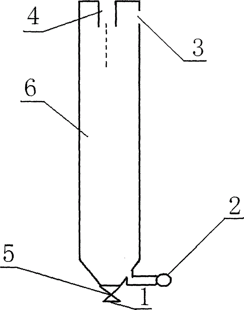
[0013] Test one: if figure 1 As shown, the high-level aspirator includes a water turbine inlet 1, a pressure gauge 2, an air inlet 3, a water inlet 4, a valve 5, and a main pipe 6 with a diameter of 20mm.

[0014] The water inlet 4 has a diameter of 5mm and an outlet diameter of 8mm;

[0015] Standard: Water in the air inlet 3 shall prevail (no flow out);

[0016] The vertical height of water vapor flowing in the pipeline (see the table below)

[0017] height (m) 1 2 3 Pressure (mPa) 0.023 0.028 0.033

[0018] The air inlet 3 shall not be smaller than the area of ​​the main pipe;

[0019] The port of the pressure gauge faces upward;

[0020] The main pipe must be vertical, otherwise it will affect the effect.

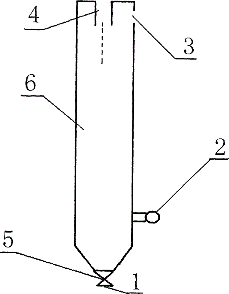
[0021] Test two: if figure 2 As shown, the high-level aspirator includes a water turbine inlet 1, a pressure gauge 2, an air inlet 3, a water inlet 4, a valve 5, and a main pipe 6 with a diameter of 20 mm.

[0022] The water inlet 4 has ...


PUM


Abstract

The invention relates to a using method of a high-position air (vapor) suction device. The high-position air suction device comprises a water pool, a water pump, a high-position air suction device and a vapor wheel generator set, wherein the high-position air suction device sucks water in the water pool to feed to the top of the high-position air suction device, the water is sprayed downwards, air is sucked at an air inlet of the high-position air suction device, pressure is formed at the bottom of a pipeline and the inlet of a water gas turbine engine, the vapor wheel generator set generates electricity, the water and air after power generation enter the water pool, the air sucked by the high-position air suction device is returned into the atmosphere over the water pool, and thus circulation is formed. The method that the high-position air suction device sucks air for pressurization lies in that, that water enters the top of the high-position air suction device is utilized, and surrounding air at the upper part of the high-position air suction device is sucked, so that the pressure is formed at the bottom of the pipeline. According to the method of generating negative pressure by the high-position (vapor) suction device, the pump is used for pumping the water in the water pool into the top of the high-position (vapor) suction device, the water is sprayed downwards, acceleration is generated due to the fact that the water is influenced by gravity of Earth, and the negative pressure is formed in an evaporator, so that a refrigerating condition is achieved.

Description

technical field [0001] The invention relates to a power generation device, in particular to a device for generating electricity and cooling by using high-level suction (steam). technical background [0002] The prior art one is that hydroelectric power stations need a certain height of water flushing hydroelectric generating units to generate electricity. The disadvantages are: the gravitational force of the earth cannot be fully utilized, and the power generation is less. The economic benefits are low. [0003] Second, steam turbine power generation not only consumes energy, but also has a lot of equipment and poor safety factor. polluted environment. [0004] The third is that the existing air conditioners all use compressors to compress and cool Freon gas to become liquid Freon, and then evaporate into gas in the evaporator. Then it is compressed and cooled by the compressor to form a cycle. The main disadvantage is the high power consumption of the compressor. evap...

Claims


Application Information

Patent Timeline
IPC IPC(8): F01D15/10F01D15/08F25B19/04
Inventor 吕仁进
Owner 吕仁进
Features
  • Generate Ideas
  • Intellectual Property
  • Life Sciences
  • Materials
  • Tech Scout
  • Unparalleled Data Quality
  • Higher Quality Content
  • 60% Fewer Hallucinations
Learn More