
Small high-speed hydraulic oil cylinder

A hydraulic cylinder and oil cylinder technology, which is applied in the field of small high-speed hydraulic cylinders, can solve problems such as difficult control of limit strokes

Inactive Publication Date: 2015-06-10
苏州洛世奇热流道科技有限公司
View PDF6 Cites 1 Cited by
  • Summary
  • Abstract
  • Description
  • Claims
  • Application Information

AI Technical Summary

Problems solved by technology

[0002] Small high-speed hydraulic cylinders are used in needle valve hot runner systems. With the development of hot runner systems, small high-speed hydraulic cylinders have been widely used in hot runner systems. The structure of small high-speed hydraulic cylinders is improved on the basis of existing common structures. Formed, the new structure is mainly improved at the following points of the prior art: 1. when several glue-feeding points on the small plastic product were relatively close to each other, the hydraulic cylinder in the needle-valve hot runner system did not space placement
2. The existing oil cylinder is not easy to control the limit stroke

Method used


Image

  • Small high-speed hydraulic oil cylinder
  • Small high-speed hydraulic oil cylinder
  • Small high-speed hydraulic oil cylinder

Examples


Embodiment Construction

[0015] The present invention will be described in detail below with reference to the accompanying drawings and in combination with embodiments.

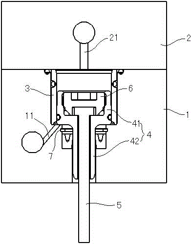
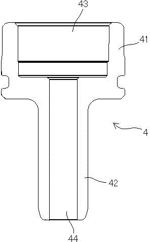
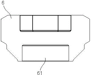
[0016] refer to figure 1 , figure 2 As shown, a small high-speed hydraulic cylinder includes a cylinder body 1 and a cylinder head 2 connected to the cylinder body 1. The cylinder body 1 is provided with a cylinder barrel 3, and the cylinder head 2 is provided with a first oil hole 21. The cylinder body 1 is provided with a second oil hole 11, the first oil hole 21 communicates with the top of the cylinder 3, and the second oil hole 11 communicates with the bottom of the cylinder 3; a piston 4 is coaxially sleeved in the cylinder 3, and the The piston 4 includes an upper end 41 and a lower end 42. The diameter of the upper end 41 is larger than that of the lower end 42. The upper end 41 is erected on the stepped surface at the bottom of the cylinder 3. The top surface of the upper end 41 is provided with a mounting groove 43, and t...


PUM


Abstract

The invention discloses a small high-speed hydraulic oil cylinder which comprises an oil cylinder body and an oil cylinder head connected to the oil cylinder body, wherein a cylinder tube is arranged in the oil cylinder body, a first oil hole is formed in the oil cylinder head, a second oil hole is formed in the oil cylinder body, the first oil hole is communicated with the top of the cylinder tube, and the second oil hole is communicated with the bottom of the cylinder tube; a piston is coaxially nested in the cylinder tube and comprises an upper end and a lower end, the diameter of the upper end is larger than that of the lower end, the upper end is erected on a step surface at the bottom of the cylinder tube, a mounting groove is formed in the top surface of the upper end, a mounting hole is formed in the bottom surface of the lower end and communicated with the mounting groove, a valve needle is arranged in the mounting groove, one end of the valve needle is erected in the mounting groove, the other end is arranged in the mounting hole, and the upper end of the valve needle is fixed in the mounting groove through a limit block; and a snap spring is connected to the outer wall of the lower end in a sleeving manner. By means of the small high-speed hydraulic cylinder, positions of rubber feed points of a small plastic product are closer, and when a needle valve hot runner system is adopted, the problem that no space is reserved for accommodating the traditional oil cylinder due to overlarge diameter can be solved with application of the cylinder.

Description

technical field [0001] The invention relates to the field of hot runner molds and injection molding, in particular to a small high-speed hydraulic oil cylinder. Background technique [0002] Small high-speed hydraulic cylinders are used in needle valve hot runner systems. With the development of hot runner systems, small high-speed hydraulic cylinders have been widely used in hot runner systems. The structure of small high-speed hydraulic cylinders is improved on the basis of existing common structures. Formed, the new structure is mainly improved at the following points of the prior art: 1. when several glue-feeding points on the small plastic product were relatively close to each other, the hydraulic cylinder in the needle-valve hot runner system did not space placement. 2. The existing oil cylinder is not easy to control the limit stroke. Contents of the invention [0003] The purpose of the present invention is to overcome the above problems in the prior art, and pro...

Claims


Application Information

Patent Timeline
Patent Type & Authority Applications(China)
IPC IPC(8): F15B15/14F15B15/20
CPCF15B15/1447F15B15/1428F15B15/24
Inventor 王小松
Owner 苏州洛世奇热流道科技有限公司
Learn More