
Stator zeroing structure of multi-redundancy angular displacement sensor and adjusting method thereof

A technology of angular displacement sensors and sensors, which is applied in the direction of instruments, measuring devices, and electrical devices, can solve the problems of insufficient release of assembly stress, waste, and large mechanical errors, and achieve the effect of improving the survival rate of products

Inactive Publication Date: 2015-06-10
FLIGHT AUTOMATIC CONTROL RES INST
View PDF5 Cites 6 Cited by
  • Summary
  • Abstract
  • Description
  • Claims
  • Application Information

AI Technical Summary

Problems solved by technology

At present, redundant angular displacement sensors are usually formed by bonding or welding the stators and the shell at one time. If the mechanical error of the parts is large and the assembly stress is not fully released, the product's one-time forming rate will be greatly reduced. At the same time, this adhesion Once the stator is fixed, it cannot be adjusted again, so that the performance requirements can only be met by replacing the entire product, resulting in unnecessary waste

Method used


Image

  • Stator zeroing structure of multi-redundancy angular displacement sensor and adjusting method thereof
  • Stator zeroing structure of multi-redundancy angular displacement sensor and adjusting method thereof
  • Stator zeroing structure of multi-redundancy angular displacement sensor and adjusting method thereof

Examples


Embodiment 1

[0025] Adjustment Method of Stator Zeroing Structure of Double Redundancy Angle Displacement Sensor

[0026] Requirements: The accuracy and other performance of each single-redundancy stator 2 has been adjusted. After the double-redundancy stator 2 is installed, the performance of the first-stage stator 2 is used as the benchmark, and the second-stage stator 2 is guaranteed to be consistent with the first-stage zero position. alignment.

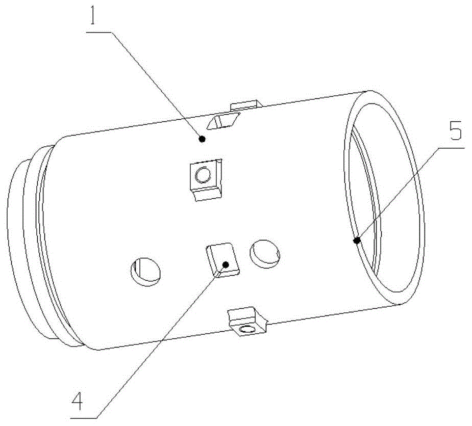
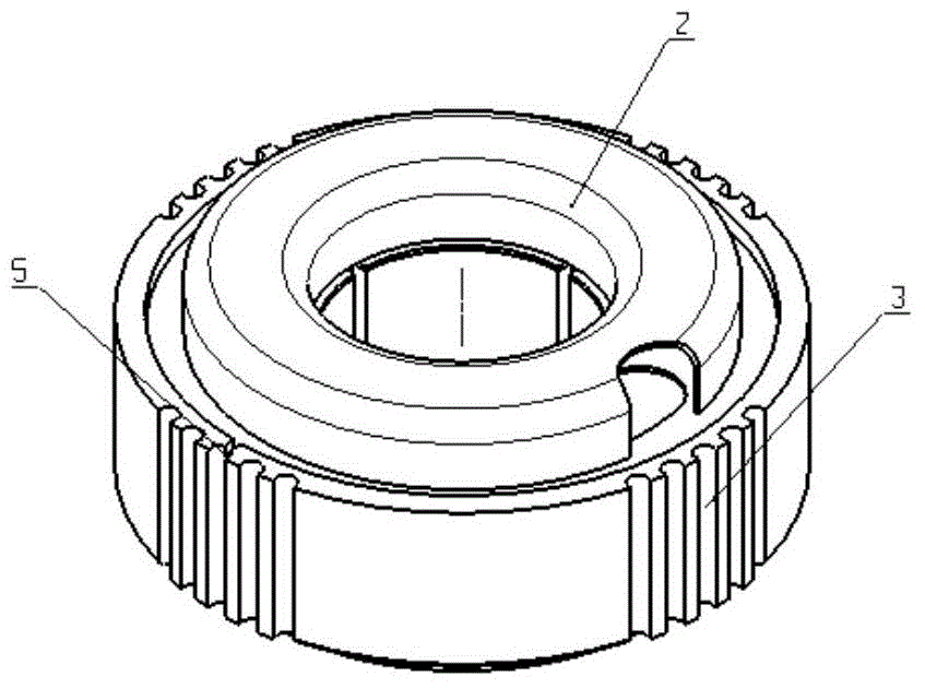
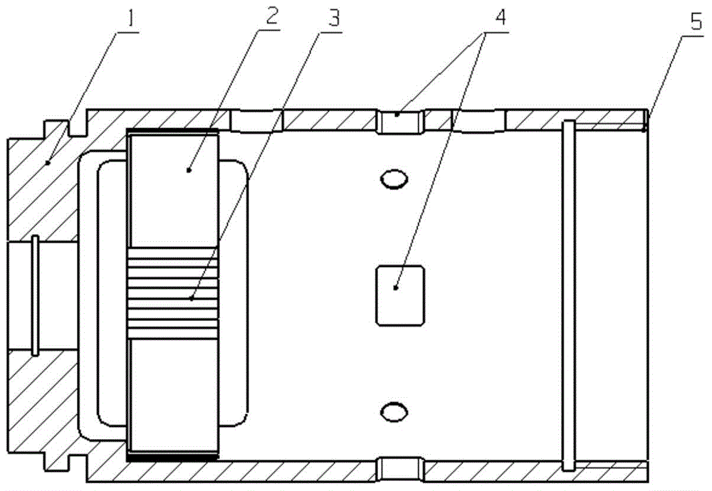
[0027] Step 1: First install the first stage stator 2; when installing, align the marking groove 5 on the stator 2 with the marking groove 5 on the sensor housing 1 and bond it to the sensor housing 1, and the rest of the stators 2 are also used to align the marking groove 5 Put it into the sensor housing 1 in the same way, but do not apply glue; make the first-stage stator 2 as the adjustment reference;

[0028] Step 2: Complete the assembly of stators 2 and other components at all levels according to the design requirements;

[0029] Step...

Embodiment 2

[0034] Adjustment Method of Stator Zero Adjustment Structure for Three Redundancy Angle Displacement Sensor

[0035] Requirements: The accuracy and other performance of each single-redundancy stator 2 has been adjusted. After the remaining two-redundancy stator 2 is installed, the performance of the first-stage stator 2 is used as the benchmark. The second-stage stator 2, the third-stage and the first-stage stage guarantees consistent zero alignment.

[0036] Step 1: First install the first stage stator 2; when installing, align the marking groove 5 on the stator 2 with the marking groove 5 on the sensor housing 1 and bond it to the sensor housing 1, and the rest of the stators 2 are also used to align the marking groove 5 Put it into the sensor housing 1 in the same way, but do not apply glue; make the first-stage stator 2 as the adjustment reference;

[0037] Step 2: Complete the assembly of stators 2 and other components at all levels according to the design requirements; ...


PUM

PropertyMeasurementUnit
Widthaaaaaaaaaa

Abstract

The invention relates to a stator zeroing structure of a multi-redundancy angular displacement sensor and an adjusting method thereof. According to a scheme, a sensor shell 1 and stators 2 are provided with a window 4 and raised tables 3; the primary stator 2 is fixed as an adjusting reference; assembly of other stators 2 and parts is finished according to design requirements; a power supply and a test set are turned on, the output voltage of the primary stator 2 and that of the other stators 2 are monitored at the same time; by adjusting the position of the raised table 3 of one stator 2, the stator 2 has minor displacement in the peripheral direction until that the minimum output zero voltage of the stator 2 and the minimum output zero voltage of the primary stator 2 are consistent. The problem that uniformity of multi-redundancy sensors is out of tolerance due to errors of parts, assembly errors and the like is solved, sensor precision is guaranteed without parts changing and reassembly, assembly and adjustment are easier, and product yield is greatly increased.

Description

technical field [0001] The invention belongs to the sensor manufacturing technology, and relates to a structure and an adjusting method for adjusting the zero position of the sensor by adjusting the position of the stator of the sensor. Background technique [0002] The performance of the conventional single-redundancy angular displacement sensor is shaped once after the parts are assembled and debugged. In recent years, with the continuous increase of user demand, the application of various redundant angular displacement sensors is also increasing. The redundant degree angular displacement sensor includes two or more stators, which requires that while satisfying the accuracy of the sensor, it is also necessary to meet the consistency of the zero performance between the stators of the sensor at all levels. At present, redundant angular displacement sensors are usually formed by bonding or welding the stators and the shell at one time. If the mechanical error of the parts is...

Claims


Application Information

Patent Timeline
IPC IPC(8): G01B7/30
Inventor 王冰周育茹马丁姚远李钰钰
Owner FLIGHT AUTOMATIC CONTROL RES INST
Learn More