
Fingerprint sensor and calibration method thereof

A fingerprint sensor and calibration method technology, which is applied in the direction of acquiring/arranging fingerprints/palmprints, instruments, printing image collection, etc., can solve problems such as shortening the service life of products, invalidation of calibration coefficients, and failure of normal use of fingerprint sensors, so as to reduce production The effect of difficulty and production cost

Active Publication Date: 2017-09-12
SHENZHEN GOODIX TECH CO LTD
View PDF4 Cites 0 Cited by
  • Summary
  • Abstract
  • Description
  • Claims
  • Application Information

AI Technical Summary

Problems solved by technology

[0018] 3), because the physical characteristics of the fingerprint sensor will change with time, and in the prior art, only one correction is performed before leaving the factory. When the physical characteristics of the fingerprint sensor change, the correction coefficient (ie k , b value) will fail, which will cause the fingerprint sensor to fail to work normally and shorten the service life of the product

Method used


Image

  • Fingerprint sensor and calibration method thereof
  • Fingerprint sensor and calibration method thereof
  • Fingerprint sensor and calibration method thereof

Examples


no. 2 example

[0114] see Figure 12 , propose the second embodiment of the calibration method of the fingerprint sensor of the present invention, the calibration method includes the following steps:

[0115] Step S200: switch to calibration mode.

[0116] Step S210: When starting the calibration, sense the fingerprint signal, and acquire the first data output by each sensing unit.

[0117] Step S220: According to the mathematical model, calculate a new correction coefficient of the corresponding sensing unit through the first data and the old correction coefficient of the corresponding sensing unit.

[0118]

[0119] b new =(1-σ)b old +σ[y-Avg(Y)]

[0120] Among them, k new and b new is the new correction coefficient of the induction unit, k old and b old is the old correction coefficient of the sensing unit, y is the first data output by the sensing unit, Y is the image composed of the first data output by all sensing units, and F(Y) is the value of the corresponding sensing uni...

no. 3 example

[0137] see Figure 13 , propose the third embodiment of the calibration method of the fingerprint sensor of the present invention, the calibration method includes the following steps:

[0138] Step S300: Determine whether the calibration condition is satisfied.

[0139]In this embodiment, the correction mode is enabled by setting correction conditions. When it is detected that the fingerprint sensor is activated for the first time, or when the preset calibration time is reached, or a calibration command is received, or the calibration effect of the old calibration coefficient does not meet the specified requirements, it is determined that the calibration conditions are met, and the calibration mode is turned on, and enters Step S310, start the calibration operation. When it is judged that the calibration condition is not met, the detection judgment is continued.

[0140] Among them, when the fingerprint sensor is enabled for the first time, the calibration mode can be set t...


PUM


Abstract

The invention discloses a fingerprint sensor and a calibration method thereof. The fingerprint sensor has a sensing surface for fingers to touch, and includes a plurality of sensing units, a processing unit and a calibration unit, wherein: the sensing unit is used to sense fingerprints when calibration starts signal and output the first data; the processing unit is used to calculate the new correction coefficient of the corresponding sensing unit through the first data according to the mathematical model; the correction unit is used to correct the second output of the corresponding sensing unit according to the new correction coefficient data. The fingerprint sensor of the present invention can automatically modify the correction coefficient when its physical characteristics change, so as to reduce the probability of product repair and prolong the service life of the product, and save the calibration link before leaving the factory, reducing production difficulty and production cost.

Description

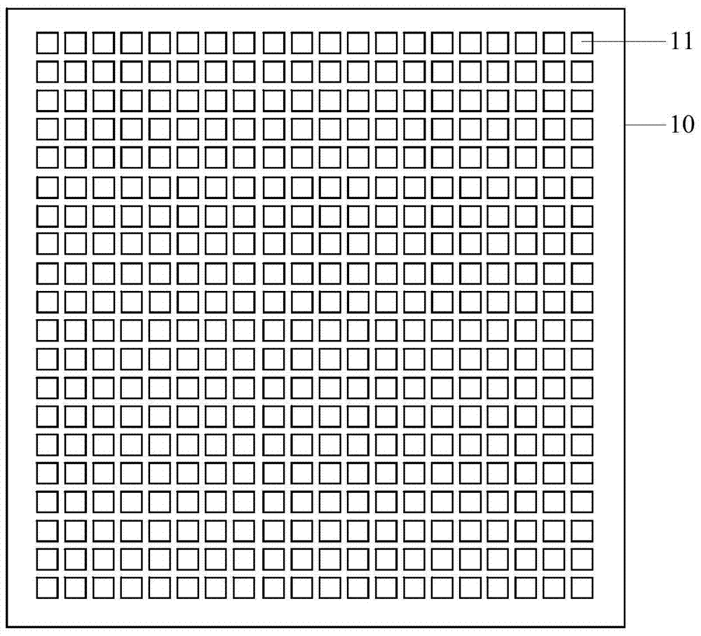
technical field [0001] The invention relates to the technical field of fingerprint identification, in particular to a fingerprint sensor and a calibration method thereof. Background technique [0002] Fingerprints are textures formed by uneven skin on the surface of fingers. The texture features of fingerprints are unique and stable, so they are often used as the basis for identification. A fingerprint sensor is a sensor that identifies an identity through a fingerprint. [0003] Such as figure 1 As shown, the fingerprint sensor includes a fingerprint sensor chip 10 and a protective cover 20 (Cover) fixed on the surface of the fingerprint sensor chip 10 by an adhesive 30 , and the protective cover 20 is used to protect the fingerprint sensor chip 10 . There are multiple sensing units 11 (Pixel) on the fingerprint sensing chip 10, such as figure 2 As shown, a plurality of sensing units 11 are arranged in a matrix, and the sensing units 11 are used to sense fingerprint sig...

Claims


Application Information

Patent Timeline
Patent Type & Authority Patents(China)
IPC IPC(8): G06K9/00G06K9/20G06V10/12
CPCG06V40/1359G06V40/1347G06V40/13G06V10/993G06V40/1306G06V10/12G06V40/1365G06F18/00
Inventor 庞树黄辉蔡小淳
Owner SHENZHEN GOODIX TECH CO LTD
Learn More