
Heat radiater for cup holder and cup holder using the same

A technology for radiators and cup holders, applied to machines that use electric/magnetic effects, machine operation methods, drinking vessels, etc., can solve problems such as difficulty in reducing base thickness, reducing heat dissipation efficiency, and heavy contact surfaces. Achieve cooling/heating performance improvement, volume and weight reduction

Active Publication Date: 2015-06-10
HYUNDAI MOTOR CO LTD
View PDF4 Cites 0 Cited by
  • Summary
  • Abstract
  • Description
  • Claims
  • Application Information

AI Technical Summary

Problems solved by technology

This makes it difficult to reduce the thickness of the base, and increases weight and cost
Weight construction is necessary to use rod heat pipes, but they are heavy and the contact surface acts as a thermal resistance, reducing heat dissipation efficiency

Method used


Image

  • Heat radiater for cup holder and cup holder using the same
  • Heat radiater for cup holder and cup holder using the same
  • Heat radiater for cup holder and cup holder using the same

Examples


Embodiment Construction

[0029] Reference will now be made in detail to various embodiments of the invention, examples of which are illustrated in the accompanying drawings and described below. While the invention has been described in conjunction with exemplary embodiments, it will be understood that present description is not intended to limit the invention to those exemplary embodiments. On the contrary, the invention is intended to cover not only the exemplary embodiments, but also alterations, modifications, equivalents and other embodiments as included within the spirit and scope of the invention as defined by the claims.

[0030] Hereinafter, embodiments of the present invention will be described with reference to the accompanying drawings.

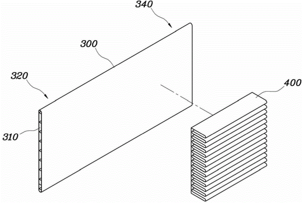
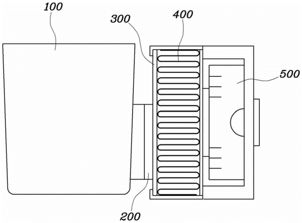
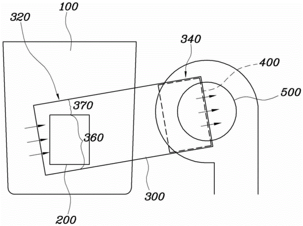
[0031] figure 1 For a view showing heat pipes and heat dissipation fins of a heat sink for a cup holder according to an exemplary embodiment of the present invention, Figure 2 to Figure 3 To show a view of a cup holder according to a first exemplary em...


PUM


Abstract

A heat radiator for a cup holder may include a heat pipe with an one end fixed in a surface contact with a heat radiation side of a thermoelectric element mounted on a body of the cup holder and another end being extended from the one end at least above the one end, heat radiation fins fixed in a surface contact with another end of the heat pipe, and a blower engaged to the another end of the heat pipe so as to enable the heat radiation fins to exchange heat.

Description

technical field [0001] The present invention relates to a heat sink for a cup holder capable of reducing weight and volume, and a cup holder using the heat sink. Background technique [0002] In existing structures where heat is dissipated through the heat dissipation side of the thermoelectric element, the thickness of the base is necessary because the area of ​​the thermoelectric element is small and the heat dissipation area is large. [0003] When the thickness is small, the heat on the heat dissipation side of the thermoelectric element is not dissipated, so that the thermal efficiency drops considerably. Furthermore, when the thickness of the base is increased, the weight of the heat sink is greatly increased and the cost of the material is also increased. [0004] In order to contact the heat pipe with the thermoelectric element, a base of the heat sink is necessary, and the heat pipe should be inserted into the base. This makes it difficult to reduce the thickness ...

Claims


Application Information

Patent Timeline
Patent Type & Authority Applications(China)
IPC IPC(8): H01L23/367H01L23/427H01L23/467
CPCB60N3/104B60N3/10F25B21/02A47G19/2288
Inventor 吴万周金才熊朴宰佑金在勋
Owner HYUNDAI MOTOR CO LTD
Learn More