
Vibration generator

A technology of vibration generator and driving coil, applied in vibration testing, fluid and electric components using vibration, etc., can solve the problems of power consumption and futility, and achieve the effect of reducing overall power consumption and enhancing excitation force.

Inactive Publication Date: 2015-06-10
EMIC LTDA
View PDF10 Cites 2 Cited by
  • Summary
  • Abstract
  • Description
  • Claims
  • Application Information

AI Technical Summary

Problems solved by technology

[0011] However, the heat generated by the excitation coil 118 and the drive coil 108 depends on the magnitude of the excitation force, etc., so always making the cooling fan 120 work at the same speed will consume power in vain.

Method used


Image

  • Vibration generator
  • Vibration generator
  • Vibration generator

Examples


Embodiment

[0115] Figure 8 It is a graph showing the relationship between the excitation force and power consumption of the vibration generator.

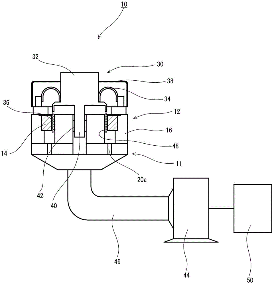
[0116] exist Figure 8 In, the graph shown as an embodiment represents the difference between the exciting force [N] and the power consumption [kW] (power consumption of the drive coil 36+power consumption of the cooling fan 44) in the vibration generator 10 of the above-mentioned embodiment. relation.

[0117] In addition, in Figure 8 , the graph shown as a comparative example represents the excitation force [N] and power consumption [kW] (power consumption of the excitation coil 118+power of the drive coil 108+power consumption of the cooling fan in the existing vibration generator 100 )The relationship between.

[0118] according to Figure 8 It is clear that the vibration generator of the present invention can significantly reduce power consumption compared with conventional vibration generators.


PUM


Abstract

[Problem] To provide a vibration generator that reduces power consumption for an entire vibration testing device and is not damaged even when intensifying the vibrating force or increasing the size of the vibration generator. [Solution] A vibration generator comprises a moving portion on which a test body is placed and a stationary portion having a magnetic circuit member, said magnetic circuit member having a magnet and a magnetic permeable yoke and being disposed so that a static magnetic field is formed in a cavity of the magnetic circuit member, and said moving portion having a driving coil and being disposed in a state where the driving coil is inserted in the cavity, and is configured so that a desired vibration is applied to the moving portion by applying a driving current to the driving coil. The vibration generator further comprises a cooling blower for cooling at least either of the magnet and the driving coil, a control device for controlling the rotational speed of the cooling blower, and a temperature measuring means for measuring the temperature of at least either of the magnet and the driving coil, and is configured so that the control device controls the rotational speed of the cooling blower on the basis of the temperature of at least either the magnet or the driving coil that was measured by the temperature measuring means.

Description

technical field [0001] The present invention relates to a vibration generator for a vibration testing device used for testing industrial products such as a vibration characteristic test, an endurance test, and more particularly, to a vibration test using a permanent magnet (hereinafter simply referred to as "magnet") to suppress power consumption A vibration generator for a device, wherein the aforementioned industrial products are, for example, aerospace equipment, automotive equipment, electronic products, precision equipment, etc. Background technique [0002] Conventionally, vibration testing using a vibration testing device has been performed in order to perform vibration characteristic tests and durability tests on industrial products such as aerospace equipment, automotive equipment, electronic products, and precision equipment. [0003] Figure 9 It is a schematic configuration diagram showing the configuration of a vibration generator of a conventional vibration tes...

Claims


Application Information

Patent Timeline
Patent Type & Authority Applications(China)
IPC IPC(8): G01M7/02
CPCG01M7/022B06B1/045H02K33/16H02K9/04H02K33/00
Inventor 井下芳雄原田和哉
Owner EMIC LTDA
Learn More