
Iron plate carving machine

A technology of engraving machines and iron plates, applied in the field of engraving machines, can solve the problems of low work efficiency and achieve the effect of improving efficiency and good guidance effect

Inactive Publication Date: 2015-06-17
徐存然
View PDF5 Cites 0 Cited by
  • Summary
  • Abstract
  • Description
  • Claims
  • Application Information

AI Technical Summary

Problems solved by technology

[0003] At present, the commonly used iron plate relief production method is manual, and the work efficiency is low.

Method used


Image

  • Iron plate carving machine
  • Iron plate carving machine

Examples


Embodiment Construction

[0013] The preferred embodiments of the present invention will be described in detail below in conjunction with the accompanying drawings, so that the advantages and features of the present invention can be more easily understood by those skilled in the art, so as to define the protection scope of the present invention more clearly.

[0014] The invention provides an iron plate engraving machine with high working efficiency.

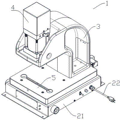
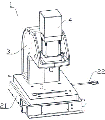
[0015] like figure 1 , figure 2 As shown, an iron engraving machine 1 includes an engraving machine body 21, a retractable power supply connection line 22 is provided on the engraving machine body 21, and a supporting body is provided on the engraving machine body 21 3. A laser 4 is provided on the support body 3, a stage 5 is also provided on the engraving machine body 21, and the laser head of the laser 4 is above the stage 5 .

[0016] like figure 1 , figure 2 As shown, the height of the laser 4 can be adjusted.

[0017] like figure 1 , fig...


PUM


Abstract

The invention discloses an iron plate carving machine which comprises a carving machine body. A stretchable power connecting line is arranged on the carving machine body. A supporting body is arranged on the carving machine body. A laser is arranged on the supporting body. An objective table is further arranged on the carving machine body. A laser head of the laser is arranged above the objective table. The height of the laser is adjustable, and the height of the objective table can be adjusted. Due to the fact that the laser which can rapidly carve patterns on the surface of an iron plate is arranged on the carving machine body, the better guiding effect is achieved during embossment manufacturing, and the embossment manufacturing efficiency is greatly improved.

Description

technical field [0001] The invention relates to an engraving machine, more precisely, an iron plate engraving machine. Background technique [0002] Iron plate relief is a traditional carving handicraft of the Han nationality. Utilizing the characteristics and primary colors of the iron plate, the uneven relief effect is knocked on the one-millimeter-thick plate. After polishing, burning and other methods, the work produces a sketch-like visual effect of black and white or with color embellishments. [0003] The iron plate relief production method generally used at present is manual, and work efficiency is low. Contents of the invention [0004] The invention mainly solves the technical problems existing in the prior art, thereby providing an iron plate engraving machine with high working efficiency. [0005] Above-mentioned technical problem of the present invention is mainly solved by following technical scheme: [0006] An iron plate engraving machine, comprising an ...

Claims


Application Information

Patent Timeline
Patent Type & Authority Applications(China)
IPC IPC(8): B23K26/36B23K26/362B44B3/00
CPCB23K26/36
Inventor 徐存然
Owner 徐存然
Learn More