liquid laminar flow processor

A technology of flow processor and liquid layer, applied in the field of liquid laminar flow processor, can solve the problems of liquid material disorder, adverse effect of liquid treatment quality, etc., and achieve the effect of uniform and controllable quality

Active Publication Date: 2017-03-15
通辽经济技术开发区农产品粗加工技术研究所
View PDF5 Cites 0 Cited by
  • Summary
  • Abstract
  • Description
  • Claims
  • Application Information

AI Technical Summary

Problems solved by technology

In the case of the same height, the material running path vertically opposite to the outlet is shorter, while the material running path at the edge staggered from the outlet is longer. Under the influence of frictional resistance, the time for the liquid at the edge to reach the outlet will be longer, so A funnel in the middle will be formed, which will inevitably cause the disorder of the liquid material in the tank and adversely affect the quality of liquid treatment.

Method used


Image

  • liquid laminar flow processor
  • liquid laminar flow processor
  • liquid laminar flow processor

Examples


Embodiment Construction

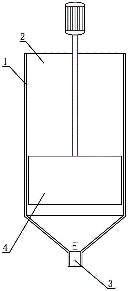
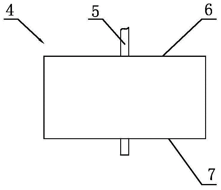
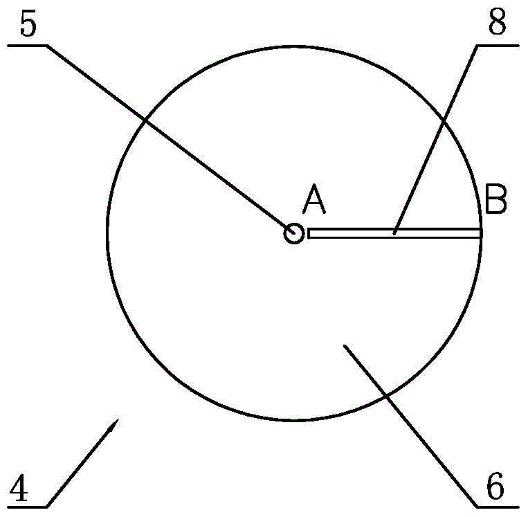
[0025] The first embodiment: as figure 1 As shown, the main body of this liquid laminar flow processor is an upright tank body 1, the tank body 1 is provided with an inlet 2 for filling liquid materials, and an outlet 3 for discharging liquid materials is provided below the tank body 1. The main body of the tank body 1 is a cylinder body, the outlet end of the lower part has a tapered shape with smaller and smaller diameters. This is basically the same as a normal tank. The difference is: the tank body 1 is provided with a cylindrical rotor 4, the outer diameter of the rotor 4 is in rotation with the inner diameter of the tank body 1, and can rotate around the rotating shaft 5 under the driving of the power machine, that is, the motor in the figure. combine figure 2 image 3 It can be seen that the upper end surface 6 of the rotor 4 is provided with a strip-shaped upper opening 8, and the upper end surface 8 extends along a radius of the upper end surface, that is, the inn...


PUM


Abstract

The invention relates to mechanical equipment, in particular to a liquid laminar flow processor. The liquid laminar flow processor comprises a vertical tank (1), the upper surface of the tank (1) is provided with an inlet (2), the lower surface of the tank (1) is provided with an outlet (3), and the end where the outlet (3) is located is in a cone shape. The liquid laminar flow processor is characterized in that a cylindrical rotor (4) is arranged in the tank (1), the outer diameter of the rotor (4) is matched with the inner diameter of the tank (1), the rotor (4) can be driven by a power machine to horizontally rotate, the upper end face of the rotor (4) is provided with a strip-shaped upper opening (8) extending to the edge along one radius of the upper end face, the lower end face of the rotor (4) is provided with a strip-shaped lower opening (9), the outer end of the lower opening (9) is opposite to the outer end of the upper opening (8) in the vertical direction, the inner end of the lower opening (9) and the inner end of the upper opening (8) are staggered, and the upper opening (8) is communicated with the lower opening (9). The liquid laminar flow processor has the advantages that lower-layer liquid is evenly scraped by the rotor in the rotating process and arrives at the outlet through the upper opening and the lower opening of the rotor, the lengths of running paths are nearly the same, running times and heights are consistent, and therefore liquid in the tank is discharged in a layered mode in sequence, processing quality is uniform and controllable, high technical requirements can be met, and the liquid laminar flow processor is especially suitable for a production system achieving continuous liquid processing operation and having a high automation and intelligence degree.

Description

technical field [0001] The present invention relates to a mechanical device, namely a liquid laminar flow processor. Background technique [0002] In industrial production, it is often necessary to process liquid materials. Most of the liquid materials are treated with tank-type equipment. The liquid enters from one end and is released from the other end after treatment. In order to use gravity, the tank body is mostly vertical, and the liquid enters from the top and is discharged from the bottom. Liquid treatment can be batch or continuous. The batch type is based on tanks. After injecting fluid materials into the tanks, the feeding is stopped. After one tank is processed, another tank is processed. The continuous type is the continuous feeding at the entrance and the continuous discharge at the exit, and the processing process is completed in the flow. Generally speaking, continuous processing has high efficiency and strong adaptability, which facilitates the formation...

Claims


Application Information

Patent Timeline
Patent Type & Authority Patents(China)
IPC IPC(8): B65D88/74
CPCB65D88/741
Inventor 张建臣
Owner 通辽经济技术开发区农产品粗加工技术研究所
Why Eureka
Try Eureka