Mixing tube and exhaust-gas disposal device with same

A technology of exhaust treatment device and mixing pipe, which is applied in the direction of exhaust device, muffler device, engine components, etc., can solve problems such as blockage of exhaust pipe, decrease of engine power performance, leakage of ammonia and ammonia, etc., to increase the evaporation distance, The effect of improving uniformity and increasing evaporation rate

Inactive Publication Date: 2015-06-17
TENNECO FAW FUSHENG CHANGCHUN AUTOMOTIVE COMPONENTS
View PDF6 Cites 10 Cited by
  • Summary
  • Abstract
  • Description
  • Claims
  • Application Information

AI Technical Summary

Problems solved by technology

If the distribution of ammonia is not uniform, it will lead to excessive ammonia in some areas, which will easily cause ammonia leakage, and the conversion efficiency of nitrogen oxides (NOx) will be too low in other ammonia-lean areas.
Uneven distribution of ammonia over a long period of time can lead to uneven catalyst aging, which affects the overall performance of the catalyst
In addition, the uneven distribution of urea droplets will cause the temperature of the local pipe wall or mixing structure to be too low, forming crystallization, which will block the exhaust pipe in serious cases and cause the engine power performance to decline

Method used


Image

  • Mixing tube and exhaust-gas disposal device with same
  • Mixing tube and exhaust-gas disposal device with same
  • Mixing tube and exhaust-gas disposal device with same

Examples


Embodiment Construction

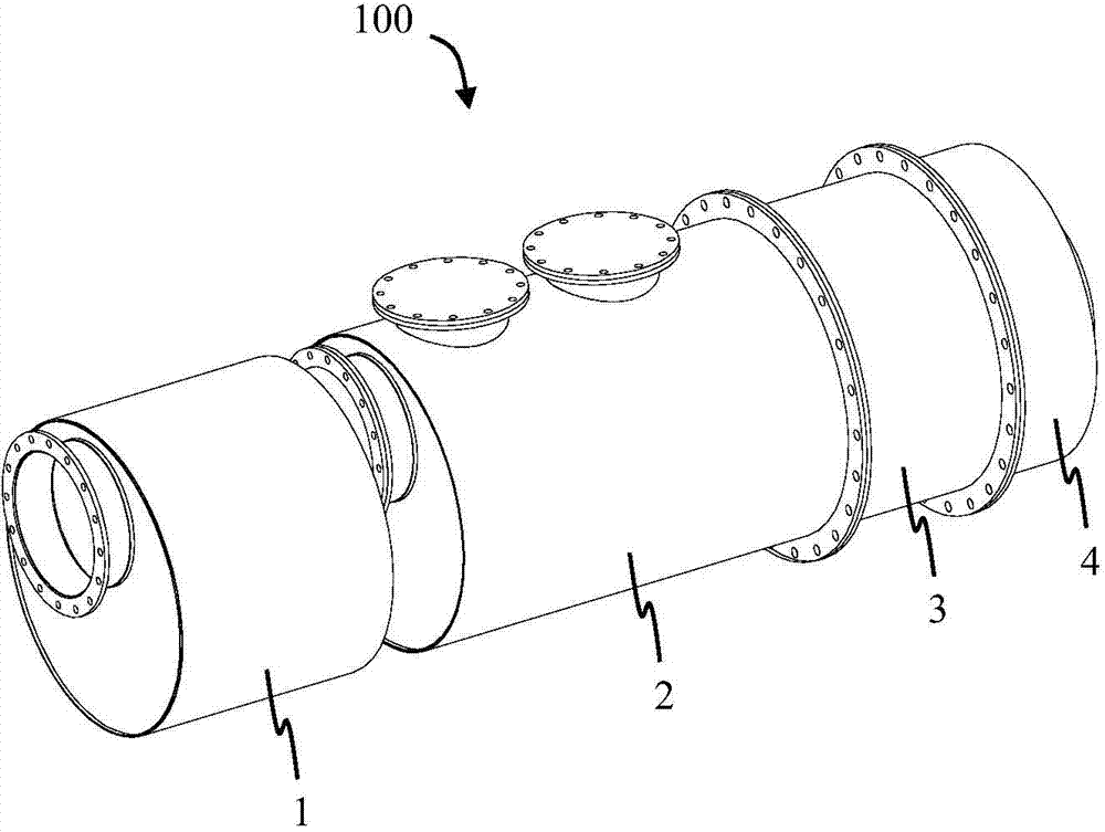
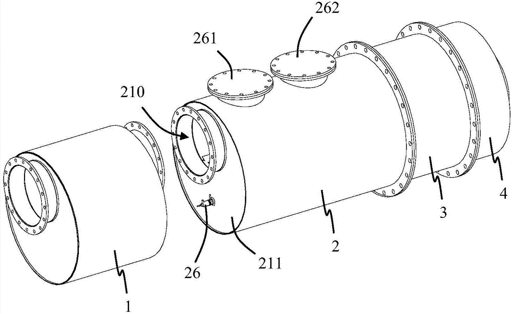
[0028] Please refer to Figure 1 to Figure 5 As shown, the present invention discloses an exhaust treatment device 100 for treating engine exhaust. The exhaust gas treatment device 100 includes a first reactor 1 , a mixing structure 2 , a second reactor 3 and a third reactor 4 . In the illustrated embodiment of the present invention, the first reactor 1 , the second reactor 3 and the third reactor 4 are arranged sequentially in the flow direction of the exhaust gas. And, functionally, the first reactor 1 is an oxidation catalyst (DOC), the second reactor 3 is a selective oxidation catalyst module (SCR), and the third reactor 4 is an ammonia leakage catalyst module (ASC). Those skilled in the art can understand that the first, second, and third reactors 1, 3, and 4 above can be designed as other types of catalytic converters or combinations according to actual needs, and details will not be repeated here.

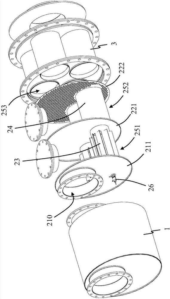
[0029] Please refer to Figure 3 to Figure 5 As shown, the mixing s...


PUM


Abstract

A mixing tube is used for an engine exhaust-gas disposal device and is of a hollow structure. An airflow inlet is formed in one end of the mixing tube, and the other end of the mixing tube is blocked; the end face of the mixing tube is helical, an airflow outlet extending in the axial direction is formed in the outer wall of the mixing tube to form exhaust gas cyclone. In this way, the travel of air in a limited space is increased, the evaporation distance of urea liquid drops is increased, the evaporation rate is improved, mixing evenness is improved, and the risk of crystallization of urea is lowered. The invention further relates to an exhaust-gas disposal device with the mixing tube.

Description

technical field [0001] The invention relates to a mixing tube and an exhaust treatment device thereof, belonging to the technical field of aftertreatment of engine exhaust. Background technique [0002] Studies have shown that the uniformity of ammonia distribution in the pipeline of exhaust aftertreatment systems (such as selective catalytic reduction systems, SCR systems) has an important impact on the overall performance and durability of the system. If the distribution of ammonia is not uniform, it will lead to excessive ammonia in local areas, which will easily cause ammonia leakage, and the conversion efficiency of nitrogen oxides (NOx) will be too low in other ammonia-lean areas. The uneven distribution of ammonia over a long period of time can lead to uneven catalyst aging, which affects the overall performance of the catalyst. In addition, the uneven distribution of urea droplets will cause the temperature of the local pipe wall or mixing structure to be too low, f...

Claims


Application Information

Patent Timeline
Patent Type & Authority Applications(China)
IPC IPC(8): F01N3/28F01N13/08
Inventor 王林曹刚王平
Owner TENNECO FAW FUSHENG CHANGCHUN AUTOMOTIVE COMPONENTS
Why Eureka
Try Eureka