Heat-removing constant-temperature structure for high-power LED lamp

A technology of LED lamps and LED lamp beads, which is applied in cooling/heating devices of lighting devices, lighting and heating equipment, semiconductor devices of light-emitting elements, etc. Death and other problems, to achieve the effect of short structure, ensuring work efficiency and life, and low manufacturing cost

Inactive Publication Date: 2015-06-17
朱惠冲
View PDF4 Cites 0 Cited by
  • Summary
  • Abstract
  • Description
  • Claims
  • Application Information

AI Technical Summary

Problems solved by technology

For example, when encountering polar climates and harsh temperature environments, the power, light output and color rendering of LED lights will easily change, which will easily cause death and cause serious consequences in actual use.

Method used


Image

  • Heat-removing constant-temperature structure for high-power LED lamp
  • Heat-removing constant-temperature structure for high-power LED lamp

Examples


Embodiment 1

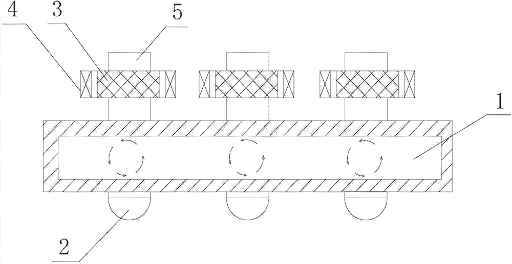
[0029] like figure 1 As shown, a heat removal and constant temperature structure of a high-power LED lamp includes: a flat gas-liquid conversion hollow cavity 1 , LED lamp beads 2 , a magnetic working medium 3 and an excitation device 4 .

[0030] Wherein, the LED lamp bead 2 is installed on one side of the gas-liquid conversion hollow cavity 1, and a hollow round tube 5 corresponding to the LED lamp bead 2 is arranged on the other side of the gas-liquid conversion hollow cavity 1, and the hollow round tube 5 is The outer protrusion, the diameter of the hollow tube 5 is consistent with the size of the substrate of the LED lamp bead 2 . The magnetic working medium 3 is arranged on the outer wall of the hollow tube 3 , and the excitation device 4 corresponds to the magnetic working medium 3 and is used to excite and demagnetize the magnetic working medium 3 .

[0031] In actual work, if the high-power LED lamp is in the ultra-negative heat working state, use the excitation devi...

Embodiment 2

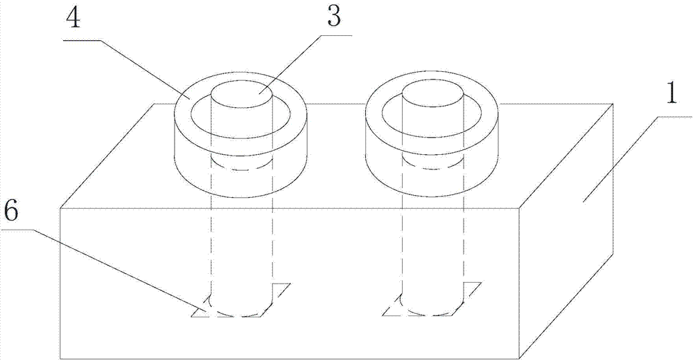
[0036] like figure 2 As shown, a heat removal and constant temperature structure of a high-power LED lamp includes: a flat gas-liquid conversion hollow cavity 1, an LED lamp bead 2, a magnetic working medium 3 and an excitation device 4; the LED lamp bead 2 is installed in the gas-liquid Invert one side of hollow chamber 1.

[0037] The structure of this embodiment is basically the same as that of Embodiment 1, the difference is that the hollow round tube is omitted, and the magnetic working medium 3 corresponding to the LED lamp bead 2 is directly provided on the other side of the gas-liquid conversion hollow cavity 1. 3 penetrates into the gas-liquid conversion hollow cavity 1 and abuts against the installation part 6 of the LED lamp bead 2. The excitation device 4 corresponds to the magnetic working medium 3 and is used to excite and demagnetize the magnetic working medium 3 .

[0038] Compared with Embodiment 1, this embodiment sets one end of the magnetic working mediu...


PUM


Abstract

The invention discloses a heat-removing constant-temperature structure for a high-power LED lamp. The structure comprises a flat gas-liquid conversion hollow cavity, wherein LED lamp beads are installed on one side of the gas-liquid conversion hollow cavity, magnetic working media corresponding to the LED lamp beads are arranged on the other side of the gas-liquid conversion hollow cavity, and excitation devices are arranged corresponding to the magnetic working media. During actual working, if the high-power LED lamp is in the overheat working state, excitation demagnetization is conducted on the magnetic working media by means of the excitation devices so that heat removal and refrigeration can be achieved; if the high-power LED lamp is in the polar region or high-altitude ultra-cold working state, intermittent constant-temperature excitation is conducted on the magnetic working media by means of the excitation devices so that constant temperature can be realized.

Description

technical field [0001] The invention relates to the application field of high-power LEDs, in particular to a heat removal and constant temperature structure for high-power LED lamps. Background technique [0002] The key technology in the application of LED is heat dissipation technology, and the quality of heat dissipation technology is directly proportional to the life and power of LED lamps. In the world, the existing LED heat dissipation technology still stays in the two aspects of material selection and heat dissipation surface area expansion. In the era of rapid development of LED technology, its excellent functions make its application fields more and more extensive, and has extended to high-end fields, such as spacecraft, aircraft, submersibles, polar expeditions, marine fish luring and other important fields. [0003] All of the above fields have extremely high requirements on the performance of LEDs, which require the stability of life, light color, and luminous f...

Claims


Application Information

Patent Timeline
Patent Type & Authority Applications(China)
IPC IPC(8): F21V29/51F21Y101/02F21Y115/10
CPCF21Y2101/00
Inventor 朱惠冲
Owner 朱惠冲
Why Eureka
Try Eureka