Insulating rod withstand voltage test testing device and locating method

A technology of testing device and withstand voltage test, which is applied in the direction of measuring device shell, testing dielectric strength, etc., can solve the problems of unrealizable structure and poor fixing effect of insulating rods, and achieves labor safety, labor intensity reduction, and normal power supply. effect of supply

Inactive Publication Date: 2015-06-17
STATE GRID CORP OF CHINA +1
View PDF0 Cites 9 Cited by
  • Summary
  • Abstract
  • Description
  • Claims
  • Application Information

AI Technical Summary

Problems solved by technology

[0002] The insulating rod belongs to the basic insulating safety equipment, through which the live equipment and the tools of the live body can be directly operated to prevent accidents during use due to performance changes or hidden dangers of the electric safety equipment during use. In the middle, the high-voltage test motor is arranged on the working part of the insulating rod. The length between the high-voltage test electrode and the ground electrode is the test length. A corresponding distance needs to be set between the high-voltage test electrode and the ground electrode to facilitate the observation of the test situation. During the test, the insulation There should be no flashover or breakdown of the rod. After the test, the insulating rod should have no trace of discharge burns and should not generate heat. At present, in the actual work process, wooden brackets are generally used to support the insulating rod, and the insulating rod is divided by the iron wire winding method. Section, this method of operation is not good for fixing the insulating rod. In fact, it is required that the insulating rod is in full contact with the voltage electrode to form an encircling contact state. This structure cannot be realized.

Method used


Image

  • Insulating rod withstand voltage test testing device and locating method
  • Insulating rod withstand voltage test testing device and locating method

Examples


Embodiment Construction

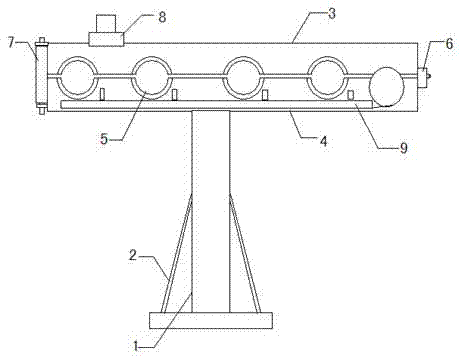
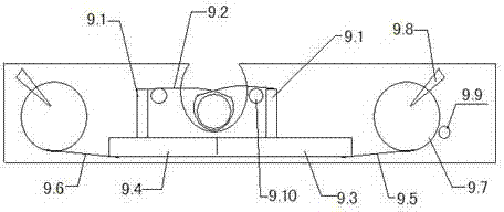
[0012] combined with Figure 1-2 , to further describe the present invention:

[0013] The present invention includes a support rod 1, a jacket, a hinge 6, and a screw rod 7. The bottom of the support rod 1 is provided with a side support frame 2, and the top of the support rod 1 is connected to a jacket, and the jacket includes an upper jacket 3 and a lower clamp. Cover 4, one end of the upper jacket 3 and the lower jacket 4 is hinged by a hinge 6, the other end of the upper jacket 3 and the lower jacket 4 is connected by a screw 7, and the upper jacket 3 and the lower jacket 4 are provided with There are semicircular grooves that cooperate with each other. The semicircular grooves inside the upper jacket 3 and the lower jacket 4 are closed to form an insulating rod through hole 5. The upper jacket 3 is provided with conductive bolts 8, so A bracket electrode closer 9 is provided between the two semicircular grooves of the lower jacket 4. The bracket electrode closer 9 ...


PUM


Abstract

The invention relates to an insulating rod withstand voltage test testing device and a locating method. According to the technical scheme, the insulating rod withstand voltage test testing device comprises a support rod, clamping sleeves, a hinge and a threaded rod, wherein the bottom of the support rod is provided with side support frames, the top of the support rod is connected with the clamping sleeves, the clamping sleeves comprise an upper clamping sleeve and a lower clamping sleeve, the upper clamping sleeve is connected with one end of the lower clamping sleeve through the hinge in a hinged mode, the upper clamping sleeve is connected with the other end of the lower clamping sleeve through the threaded rod, the upper clamping sleeve and the lower clamping sleeve are provided with semicircular grooves which are mutually matched, insulating rod through holes are formed after the semicircular grooves in the upper clamping sleeve and the lower clamping sleeve are closed, the upper clamping sleeve is provided with a conducting bolt, and a support electrode closer is arranged between every two semicircular grooves. The insulating rod withstand voltage test testing device and the locating method have the advantages that the labor safety of personnel is guaranteed, the installing efficiency is improved, the labor intensity of construction personnel is reduced, the normal operation of a transformer is guaranteed, and normal power supply is supplied.

Description

technical field [0001] The invention relates to a transformer protection device, in particular to a testing device and a positioning method for an insulating rod withstand voltage test. Background technique [0002] The insulating rod belongs to the basic insulating safety equipment, through which the live equipment and the tools of the live body can be directly operated to prevent accidents during use due to performance changes or hidden dangers of the electric safety equipment during use. In the middle, the high-voltage test motor is arranged on the working part of the insulating rod. The length between the high-voltage test electrode and the ground electrode is the test length. A corresponding distance needs to be set between the high-voltage test electrode and the ground electrode to facilitate the observation of the test situation. During the test, the insulation There should be no flashover or breakdown of the rod. After the test, the insulating rod should have no trac...

Claims


Application Information

Patent Timeline
Patent Type & Authority Applications(China)
IPC IPC(8): G01R31/12G01R1/04
Inventor 刘文华
Owner STATE GRID CORP OF CHINA
Why Eureka
Try Eureka