
Charging system and charging station for electric vehicle

A charging system, electric vehicle technology, applied in electric vehicles, battery circuit devices, current collectors, etc., can solve the problem of not having emergency charging

Inactive Publication Date: 2015-06-17
STATE GRID CORP OF CHINA +2
View PDF8 Cites 1 Cited by
  • Summary
  • Abstract
  • Description
  • Claims
  • Application Information

AI Technical Summary

Problems solved by technology

[0009] Embodiments of the present invention provide a charging system and charging station for electric vehicles, to at least solve the technical problem that the existing charging systems for electric vehicles do not have the function of emergency charging

Method used


Image

  • Charging system and charging station for electric vehicle
  • Charging system and charging station for electric vehicle
  • Charging system and charging station for electric vehicle

Examples


Embodiment 1

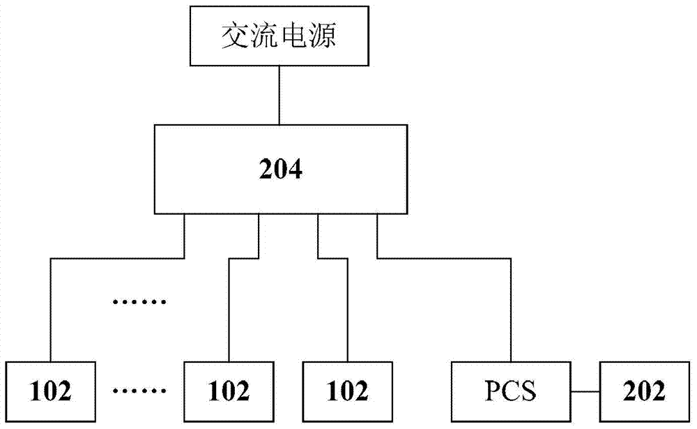
[0031] According to an embodiment of the present invention, a charging system for electric vehicles is provided, such as figure 2 As shown, the system includes:

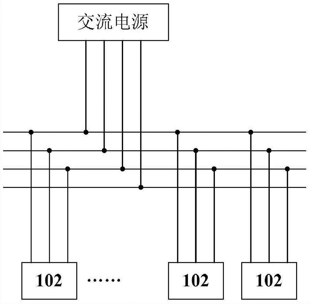
[0032] 1) N DC charging devices 102, each of the N DC charging devices 102 includes an AC / DC converter and an interface device provided at the DC output end of the AC / DC converter, and the interface device is used to plug in the DC power of the electric vehicle. charging interface;

[0033] 2) The power conversion system PCS and the battery pack 202 connected to the PCS;

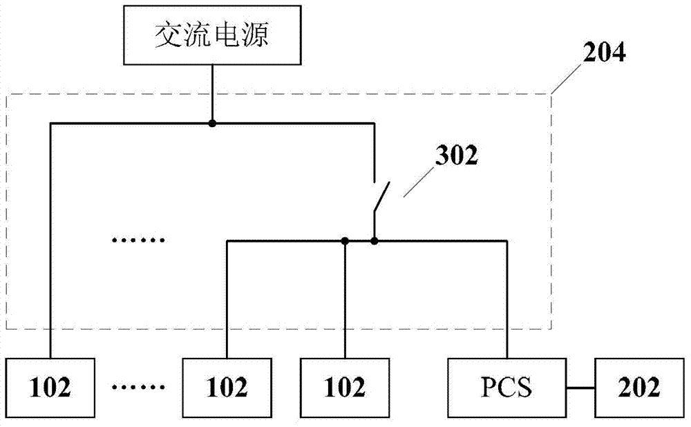
[0034] 3) The connecting device 204 is connected between the AC power source and the N DC charging devices 102 and the PCS. When the connecting device 204 is in the first state, the N DC charging devices 102 and the PCS are all connected to the AC power source. The connecting device 204 In the second state, M DC charging devices 102 among the N DC charging devices 102 are connected to the PCS, and M is smaller than N.

[0035] It should be clea...

Embodiment 2

[0058] According to an embodiment of the present invention, a charging station for an electric vehicle is also provided, the charging station includes:

[0059] 1) The charging system for electric vehicles as described in Example 1.

[0060] In the embodiment of the present invention, since the PCS and the battery pack can play the role of energy storage, when the power grid cannot supply power normally, the electric vehicle to be charged can also be charged through the electrical connection between the PCS and the battery pack and the DC charging device. In other words, the above-mentioned charging system provides the function of emergency charging, thereby solving the problem that the existing electric vehicle charging system does not have the function of emergency charging.

[0061] In addition, in the embodiment of the present invention, various improvements to the charging system described in Embodiment 1 can also be combined, and the charging station implementing the cha...


PUM


Abstract

The invention discloses a charging system and a charging station for an electric vehicle. The system comprises N DC charging devices, an electric energy converting system PCS, a battery pack and a connecting device, wherein each DC charging device comprises an AC / DC converter and an interface device arranged at the DC output end of the AC / DC converter, and the interface devices are used for being connected with a DC charging interface of the electric vehicle in an inserted mode; the battery pack is connected with the PCS; the connecting device is connected between an AC power source on one side and the N DC charging devices and the PCS on the other side; when the connecting device is in a first state, the N DC charging devices and the PCS are connected with the AC power source; when the connecting device is in a second state, M of the N DC charging devices are connected with the PCS, wherein M is smaller than N. The charging system and the charging station solve the technical problem that an existing charging system for the electric vehicle does not have the emergency charging function.

Description

technical field [0001] The invention relates to the field of electric vehicles, in particular to a charging system and a charging station for electric vehicles. Background technique [0002] Under the background that the pollution caused by vehicle exhaust to urban air is becoming more and more difficult to ignore, electric vehicles, as a high-efficiency, energy-saving and low-emission alternative to traditional vehicles, have become a hot spot of concern. For now, the development of the electric vehicle industry depends to a considerable extent on the simultaneous construction of supporting energy supply infrastructure. Among them, because the domestic theory of charging station planning and design is not perfect, it is still in the demonstration and exploration stage, so At the current stage, the system optimization design of charging stations is the key research content of infrastructure construction, which plays a vital role in the implementation of project construction,...

Claims


Application Information

Patent Timeline
IPC IPC(8): H02J7/00H02J7/02
Inventor 焦东升李香龙陈强朱杰迟忠君赵建勇张昌斌曾爽杜岩平王永勤张兴汉郭会青
Owner STATE GRID CORP OF CHINA
Learn More