Dust removal unit

A driven shaft and base plate technology, applied in the manufacture of stator/rotor bodies, etc., can solve the problems of multiple processing and assembly procedures, low efficiency, complex and cumbersome processes, etc., and achieve the effect of reasonable structure and high efficiency

Active Publication Date: 2017-08-08
东莞市森江机电科技有限公司
View PDF7 Cites 0 Cited by
  • Summary
  • Abstract
  • Description
  • Claims
  • Application Information

AI Technical Summary

Problems solved by technology

[0003] At present, domestic motor assembly in this area is still done by manual bare hands + simple devices or small semi-automatic equipment. The more difficult it is, these factors have become the main obstacles restricting the manufacturing and assembly of motors. Therefore, domestic large and medium-sized motor manufacturing factories urgently need automatic assembly machines

Method used


Image

  • Dust removal unit
  • Dust removal unit
  • Dust removal unit

Examples


Embodiment

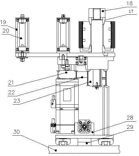
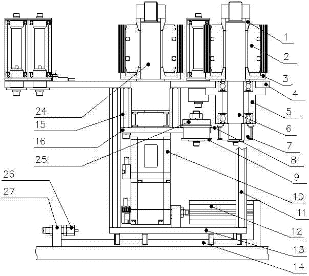
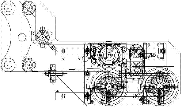
[0020] A dust removal unit: In the schematic structural diagram, it is divided into three parts: a tape clamping mechanism, a tape roller transmission mechanism and a dust removal driving mechanism, all of which are fixed on the base plate 30 of the equipment machine. The tape clamping mechanism includes a bottom plate 13 provided with installation references for various parts. The support plate 4 is mounted on the bottom plate 13 by a bracket 11, and the bearing seat 5 supporting the first driven shaft 6 is fixed under the support plate 4. The sleeve 2 is installed on the first driven shaft 6, the clamp base 3 and the tension sleeve 1 are installed on the two ends of the sleeve 2 on the first driven shaft 6, and the lock nut 18 is installed on the shaft end of the first driven shaft 6. At the thread, the fixed handle 17 is installed on the lock nut 18, and the third driven wheel 19 is fixed to the support plate 4 by the fourth driven shaft 20; the belt roller transmission mecha...


PUM


Abstract

The invention relates to automatic assembly production equipment for the internal rotor structure of a DC motor of a household appliance, specifically a dust removal unit of a motor rotor assembly line. The base plate is provided with a linear guide rail, and the base plate is provided with a tape clamping mechanism and a tape roller transmission mechanism. and the dust removal drive mechanism, the bracket of the tape clamping mechanism is set on the base plate, the support plate is provided on the support plate, and the first driven shaft and the second driven shaft are arranged side by side on one side of the support plate, the first driven shaft and the second driven shaft The driven shafts are respectively provided with pulleys and are connected by belts. The first driven shaft and the second driven shaft are respectively covered with sleeves. The drive motor is installed on the bracket. The driven shaft and the fourth driven shaft, the third driven shaft and the fourth driven shaft are respectively provided with sleeves, the first driven shaft or the second driven shaft is provided with a tape roll on the tension sleeve, and the The base plate is provided with a cylinder support, and the compression cylinder is installed on the cylinder support, which has the advantages of reasonable structure and high working efficiency.

Description

Technical field [0001] The invention relates to an automatic assembly production equipment for the internal rotor structure of a DC motor of a household appliance, in particular to a dust removal unit of a motor rotor assembly line. Background technique [0002] We know that with the improvement of the quality of life of the people, people’s demand for air conditioners, washing machines and other household appliances is increasing and the requirements are getting higher and higher, and whether the production of the core power unit (motor) of these appliances can meet the quality, The demand for quantity is crucial. [0003] At present, the domestic motor assembly in this area is still completed by manual bare hands + simple devices or small semi-automatic equipment. The efficiency is very low. Due to the many processing and assembly procedures and the complex and cumbersome process, a large number of skilled operators are required and more and more workers are hired. The more diff...

Claims


Application Information

Patent Timeline
Patent Type & Authority Patents(China)
IPC IPC(8): H02K15/02
Inventor 李志理谭光政钟育旋阎宏伟
Owner 东莞市森江机电科技有限公司
Why Eureka
Try Eureka