Optical module

An optical module, the first technology, applied in the field of optical modules, can solve the problem that the operating temperature of the optical module cannot meet the industrial-grade operating temperature range, etc.

Active Publication Date: 2015-06-17
HISENSE BROADBAND MULTIMEDIA TECH
View PDF2 Cites 8 Cited by
  • Summary
  • Abstract
  • Description
  • Claims
  • Application Information

AI Technical Summary

Problems solved by technology

[0009] The embodiment of the present invention provides an optical module, which can solve the problem in the prior

Method used


Image

  • Optical module
  • Optical module
  • Optical module

Examples


Embodiment Construction

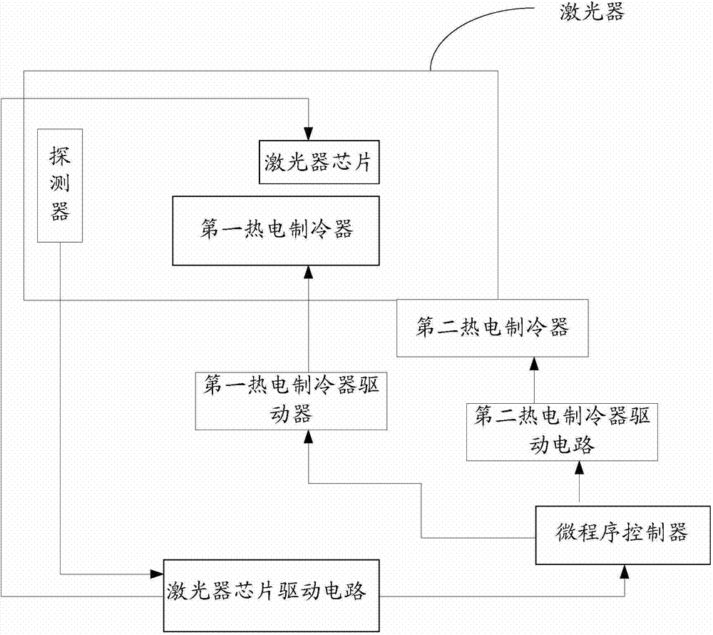
[0022] The optical module in the embodiment of the present invention includes a first thermoelectric cooling TEC, the first TEC is arranged inside the laser, and the first TEC is used for heating or cooling according to the input start signal of the microprogram controller MCU; the first Two TECs, the second TEC is arranged on the shell of the laser, and the second TEC is used for heating or cooling according to the MCU input start signal; The magnitude of the operating current input by the chip determines whether to input the on or off signal to the first TEC and the second TEC. In the above-mentioned embodiment, the first TEC is arranged inside the laser, and the second TEC is arranged on the laser shell. The first TEC and the second TEC can perform heating or cooling operations according to the start signal input by the MUC, wherein the MCU drives the circuit according to the laser chip. The magnitude of the working current input to the laser chip controls the working state...


PUM


Abstract

The invention discloses an optical module. The optical module mainly comprises a first thermoelectric cooler (TEC) and a second TEC. The first TEC is arranged inside a laser, and the first TEC is used for inputting starting signals to conduct heating or cooling according to a micro control unit (MCU). The second TEC is arranged on a shell of the laser, and the second TEC is used for inputting the starting signals to conduct heating or cooling according to the MCU. The MCU is used for deciding to input starting or shutdown signals to the first TEC and the second TEC according to the magnitude of the working current which is input to a laser chip by a laser chip driving circuit. By the adoption of the method, the operating temperature of the optical module can be kept within a constant range, and thus the operating failure of the optical module can be avoided.

Description

technical field [0001] The invention relates to the technical field of optical fiber communication, in particular to an optical module. Background technique [0002] At present, an EPON (Ethernet Passive Optical Network, Ethernet Passive Optical Network) OLT (Optical Line Terminal, Optical Line Terminal) optical module is usually a multi-channel receiving and receiving optical device integrating a transmitting channel and a receiving channel. [0003] figure 1 An exemplary structure diagram of an asymmetric mode 10G EPON OLT is shown, which includes a single optical fiber 10, a coaxial package DFB (Distributed Feed Back, distributed feedback laser) 11, a first filter 12, a coaxial package light receiving Assembly 13 , second filter 14 , external lens 15 , EML laser 16 and horizontal axis 17 . Among them, the EML (Electro-absorption modulated laser, cooled laser) 16 is used to emit the first downlink optical signal λ1 with a converged light rate of 10Gb / s, and its wavelengt...

Claims


Application Information

Patent Timeline
IPC IPC(8): H04B10/40
CPCH01S5/02212H01S5/02415H01S5/06804H01S5/4012H01S5/02251
Inventor 张强赵其圣金成浩
Owner HISENSE BROADBAND MULTIMEDIA TECH
Why Eureka
Try Eureka