a fire extinguishing device

A technology of fire extinguishing device and fire extinguishing agent, which is applied in the direction of fire rescue, etc., can solve the problems of high production cost of fire extinguishing device, difficulty in general use of main accessories of fire extinguishing products, difficulty in mass production of accessories, and mechanized production, so as to achieve better fire extinguishing effect and convenient Batch production, the effect of automatic production

Active Publication Date: 2018-05-22
CNBCC AUTOMOBILE SPARE PART XIAMEN
View PDF9 Cites 0 Cited by
  • Summary
  • Abstract
  • Description
  • Claims
  • Application Information

AI Technical Summary

Problems solved by technology

However, the fire extinguishing devices of the prior art generally have the following problems: the main accessories of fire extinguishing products of various specifications are difficult to be used in common, which makes it difficult to realize batch and mechanized production of the accessories, thus resulting in higher production costs of the fire extinguishing devices of the prior art

Method used


Image

  • a fire extinguishing device
  • a fire extinguishing device
  • a fire extinguishing device

Examples


Embodiment 1

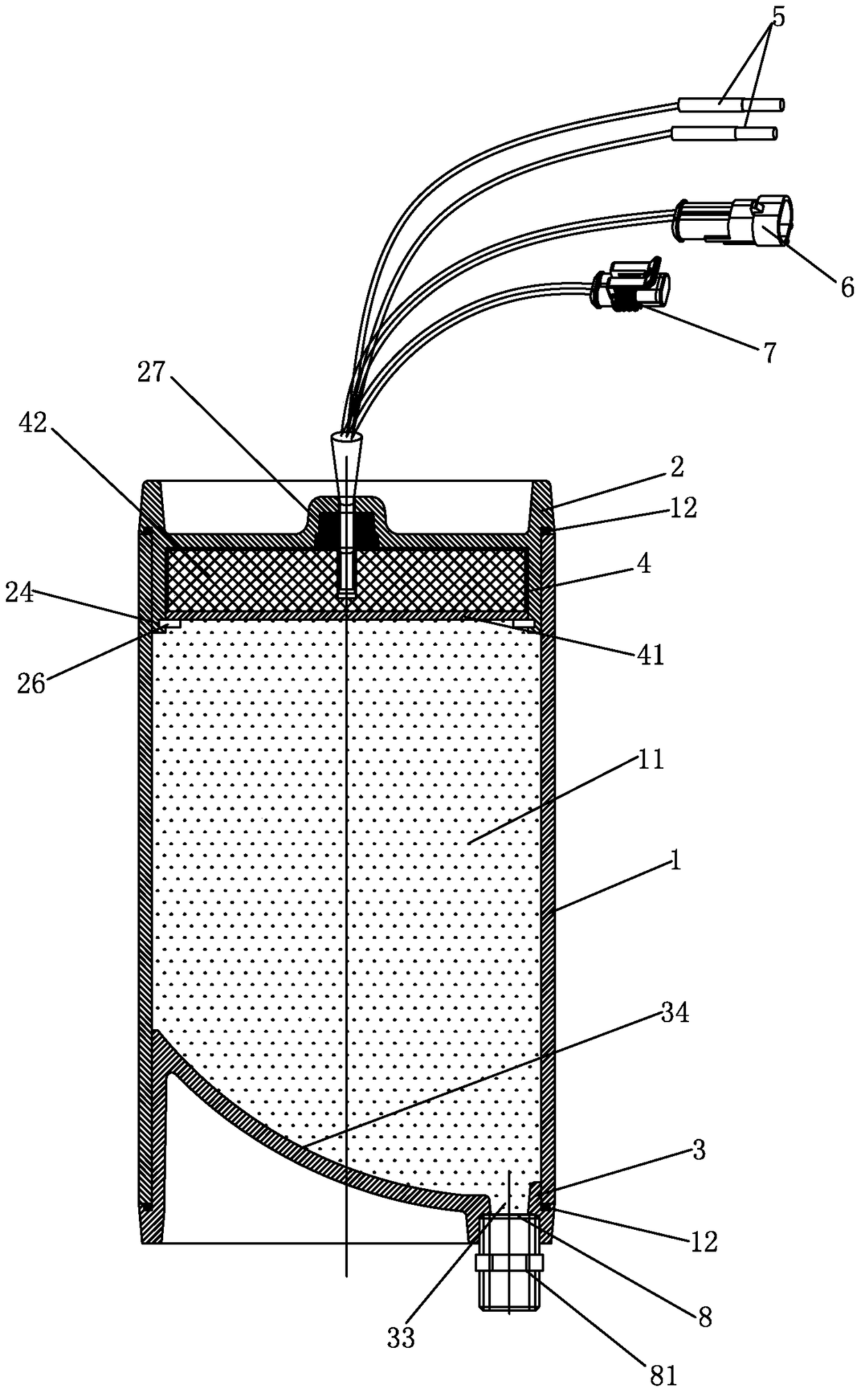
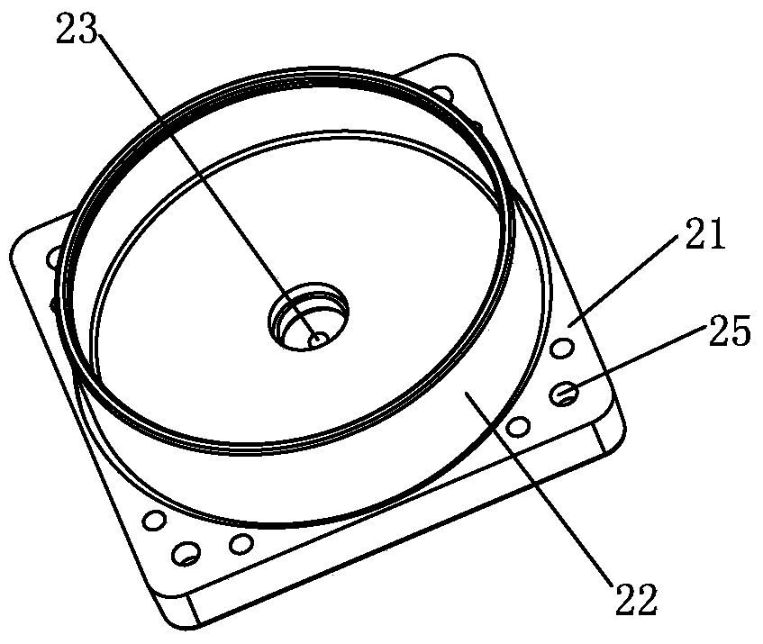
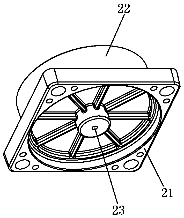
[0048] See Figure 1-Figure 5 As shown, a fire extinguishing device of the present invention, the shell of the fire extinguishing device includes a cylinder body 1 , a first end cover 2 and a second end cover 3 that are open at both ends and are not deformed or cracked when activated. Wherein, cylinder body 1 adopts stainless steel pipe or cold-drawn cold extruded aluminum alloy pipe, and the cross-sectional shape of the periphery of this cylinder body 1 is rectangle (such as figure 2 As shown, this is a cold-drawn and cold-extruded aluminum alloy tube; or, the cross-sectional shape of the outer circumference of the cylinder 1 can also be circular, oval, etc.), and the cross-sectional shape of the inner circumference is circular. The first end cover 2 and the second end cover 3 are produced by moulds, which have good consistency and stability in performance and size. The first end cover 2 is sealingly connected to the opening at one end of the cylinder body 1, and the second...

Embodiment 2

[0063] See Figure 19 As shown, a fire extinguishing device of the present invention differs from Embodiment 1 in that the fire extinguishing agent nozzle 33 of the second end cover 3 is located at the center of the second connection seat 31, and the guide portion 32 on the The guide surface 34 is in the shape of a spherical crown.

Embodiment 3

[0065] See Figure 20 As shown, a fire extinguishing device of the present invention differs from Embodiment 1 in that the outer diameter of the annular side wall 22 of the first end cover 2 is smaller than the inner diameter of the cylinder 1, that is, when the first end cover 2 is sealed When connected to the cylinder 1 , the outer peripheral side of the annular side wall 22 is not in close contact with the inner wall of the cylinder 1 .


PUM


Abstract

The invention discloses a fire extinguishing device. A shell of the fire extinguishing device comprises a cylinder, a first end cover and a second end cover, wherein the two ends of the cylinder are opened, and the cylinder cannot deform and crack after being started, wherein the first end cover is tightly connected with the opening in one end of the cylinder and the second end cover is tightly connected with the opening in the other end of the cylinder so that a fire extinguishing agent chamber is defined; a fire extinguishing agent nozzle and a guide surface for the movement of the fire extinguishing agent are arranged on the second end cover, wherein the guide surface comprises a guide curved surface and / or a guide inclined surface. By adopting the structure, the mass production is convenient and the production cost is saved; the first end cover, the second end cover and the other accessories are not changed, the mass production can be realized and the device is good in performance, size uniformity and stability; the product seriation of the near standards can be realized only by changing the length of the cylinder, so that different dosages of the fire extinguishing agents can be produced; the redesign is unnecessary, the production of the cylinder is simple and the automatic production can be simply realized.

Description

technical field [0001] The invention relates to the field of fire fighting, in particular to a fire extinguishing device. Background technique [0002] With the rapid development of the national economy and the continuous improvement of people's livelihood and safety awareness, fire-fighting equipment has been widely used, and fire-fighting facilities and fire-extinguishing devices are also equipped in many occasions. However, the fire extinguishing devices of the prior art generally have the following problems: the main accessories of fire extinguishing products of various specifications are difficult to use, which makes it difficult to realize batch and mechanized production of the accessories, resulting in high production costs of the fire extinguishing devices of the prior art. Contents of the invention [0003] The invention provides a fire extinguishing device, which overcomes the disadvantage that the main accessories of the fire extinguishing device in the prior ar...

Claims


Application Information

Patent Timeline
Patent Type & Authority Patents(China)
IPC IPC(8): A62C37/11
CPCA62C31/02A62C37/11
Inventor 洪伟艺许燕青吴添林
Owner CNBCC AUTOMOBILE SPARE PART XIAMEN
Why Eureka
Try Eureka